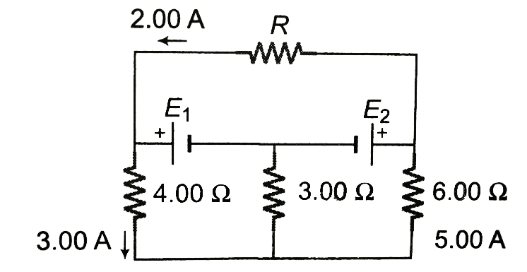
In the circuit shown in figure, are tow ideal sources of unknown emfs. Some currents are shown. Potential differences appearing across resistance is
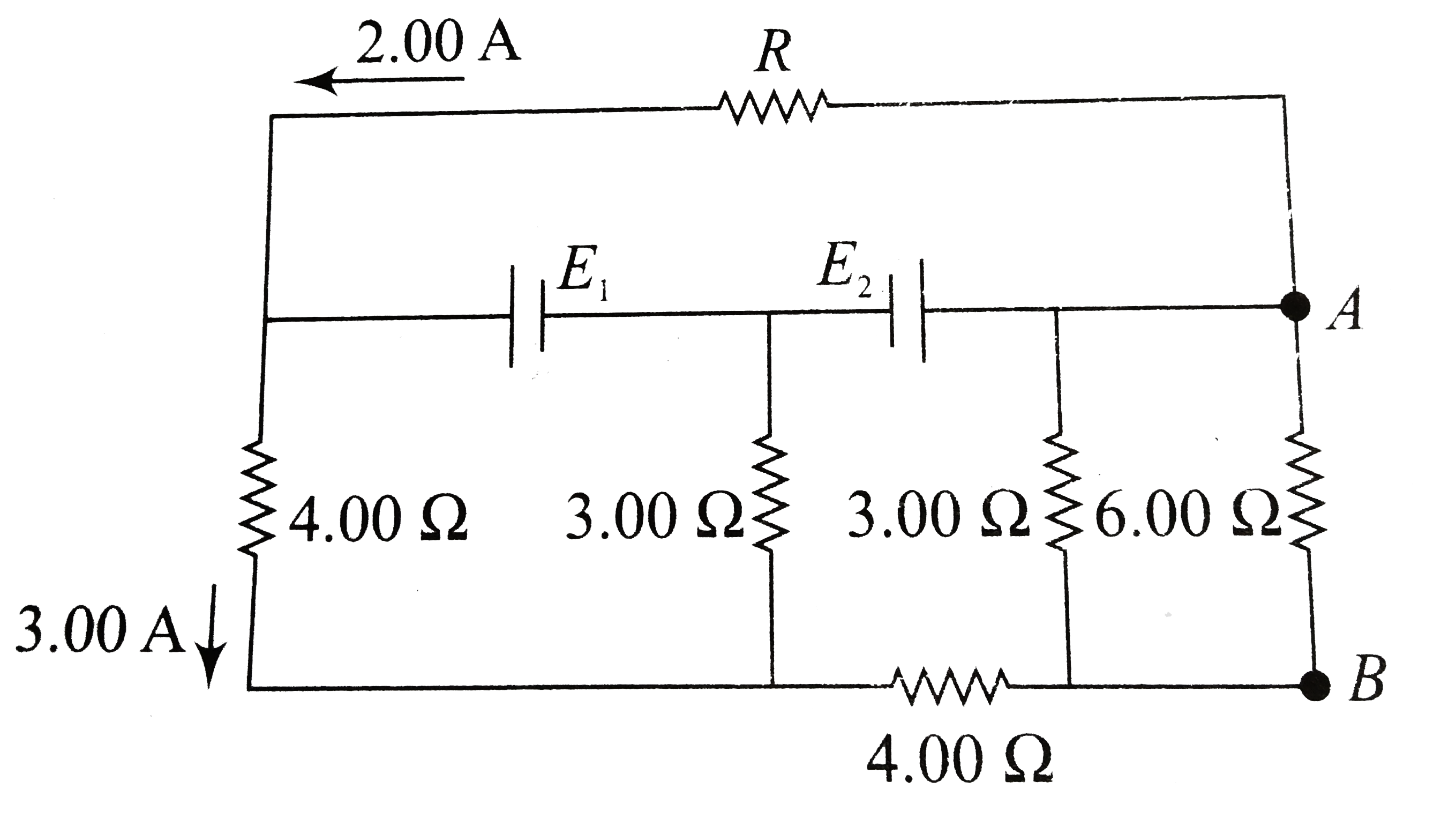
The current in the resistance between C & B is 5A.
The unknown emf is 36 V.
The unknown emf is 54 V.
the resistance R is equal to .

after redrawing the circuit
(a)
(b) From loop (1) to (1)
volt from loop to
volt
(c) from loop (3) to (3)
Topper's Solved these Questions
Similar Questions
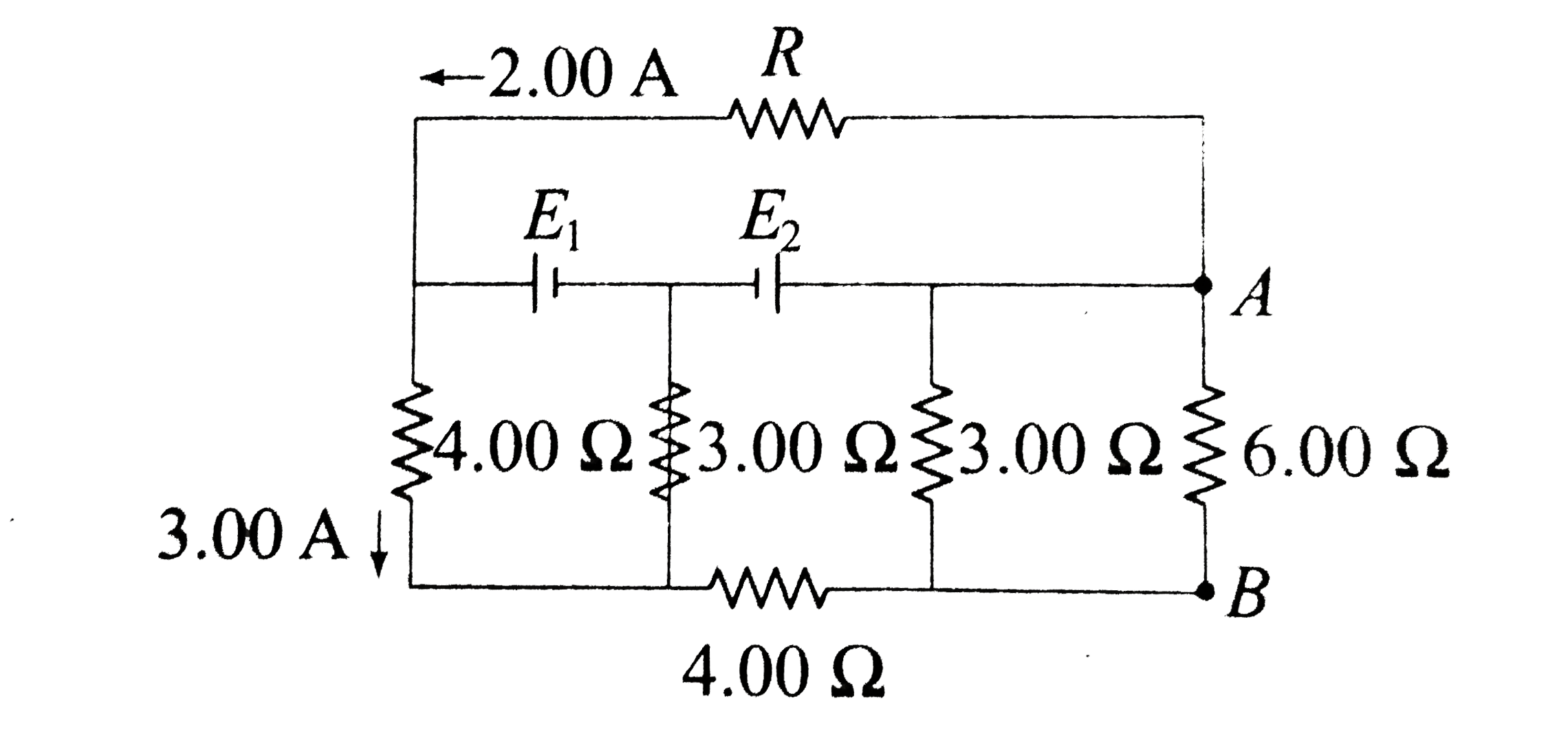
In the circuit shown in figure, E1andE2 are two ideal sources of unknown emfs. Some currents are shown. Potential difference appearing across 6Ω resistance is VA−VB=10V.
 View Solution
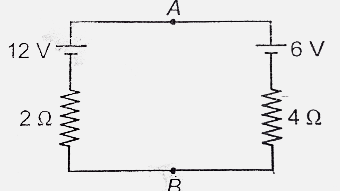
Potential difference across AB , i.e., VA−VB is
 View Solution
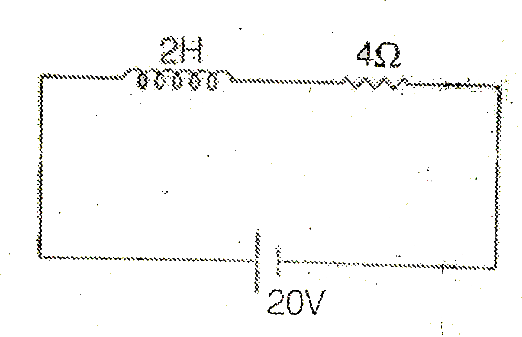
In the L-R circuit as shown in figure, potential difference across the resistance at some instant is 4 V. Then
 View Solution
In the circuit shown in fig. the cell is ideal with emf 15V. Each resistance is of 3Ω. The potential difference across the capacitoro in steady state is
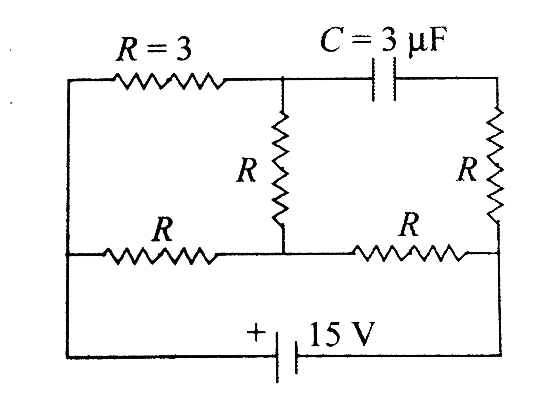 View Solution
In the circuit shown, the currents I1 and I2 are if the applied potential is of 12V,internal resistance 1 ohm:
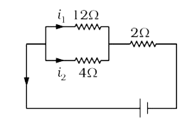 View Solution
In the circuit shown in fig. the cell has emf 10V and internal resistance 1Ω
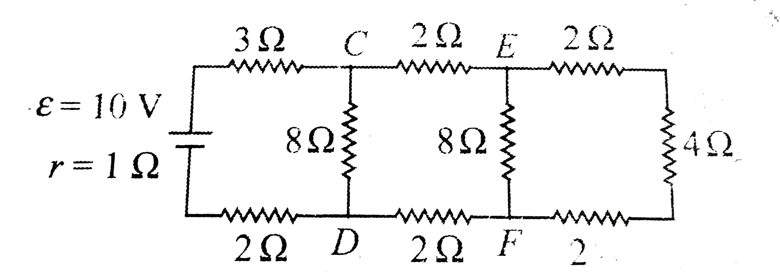 View Solution
In the circuit shown in figure
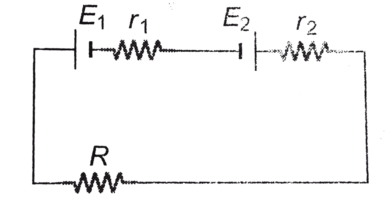
E1=10V,E2=4V,r1=r2=1Ω and R=2Ω.
Find the potential difference across battery 1 and battery 2.View SolutionIn the circuit shown in figure

E1=10V,E2=4V,r1=r2=1Ω and R=2Ω.
Find the potential difference across battery 1 and battery 2.View SolutionIn the circuit shown in figure find:
a. the current in the 3.00Ω resistor,b. the unknown emfsE1 and E2 and c the resistance R.View SolutionIn the circuit shown in the figure , no current flows through the 8Omega resistor, then the potential difference between points A and B(V_A - V_B) is
_PHY_E01_001_Q01.png) View Solution
View Solution

