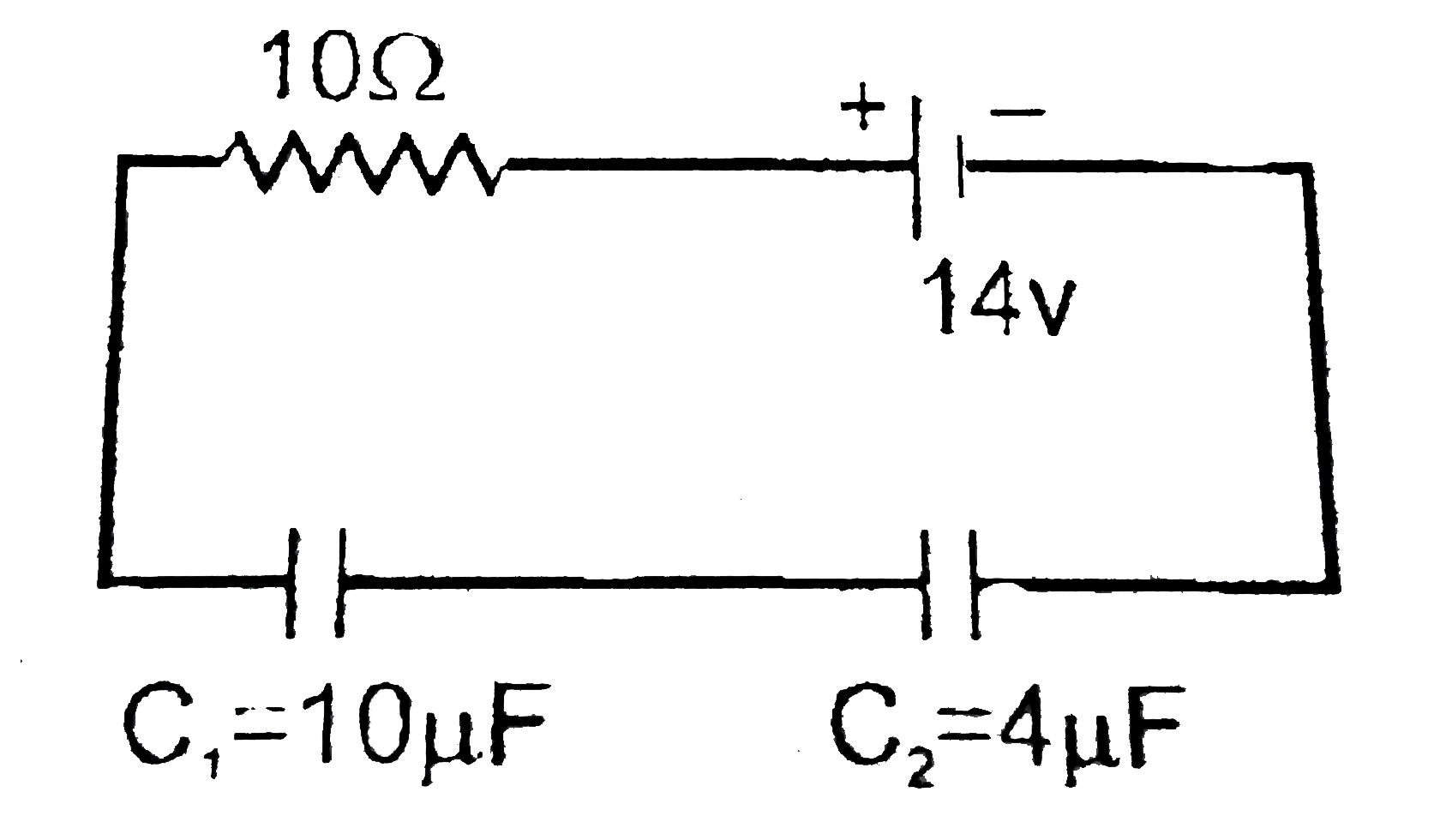
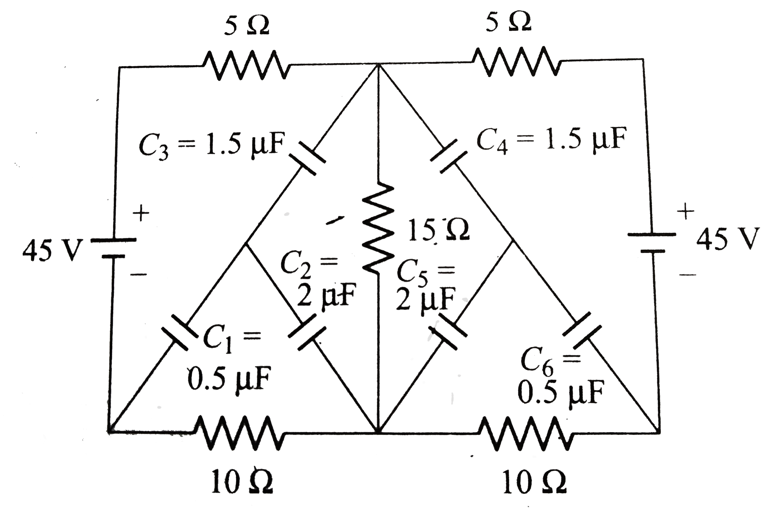
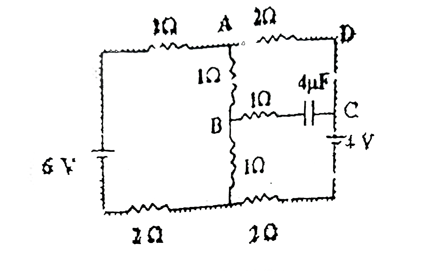
In the given circuit, in steady state we may say: (capacitor are initially uncharged)
potential drop across the capacitor C1 is 4V
potential drop across 10Ω resistance 10V
charge on C1 and C2 is 20μC
ratio of carge on C1 and C2 is 1
NA
Topper's Solved these Questions
- TEST PAPERSBOOK - RESONANCE ENGLISHCHAPTER - TEST PAPERSEXERCISE - PART - II PHYSICS
106 Videos
- SIMPLE HARMONIC MOTION BOOK - RESONANCE ENGLISHCHAPTER - SIMPLE HARMONIC MOTION EXERCISE - Advanced Level Problems
13 Videos
- TEST SERIESBOOK - RESONANCE ENGLISHCHAPTER - TEST SERIESEXERCISE - PHYSICS
130 Videos
Similar Questions
In the given circuit, in steady state we may say: (capacitors are initially unchanged)
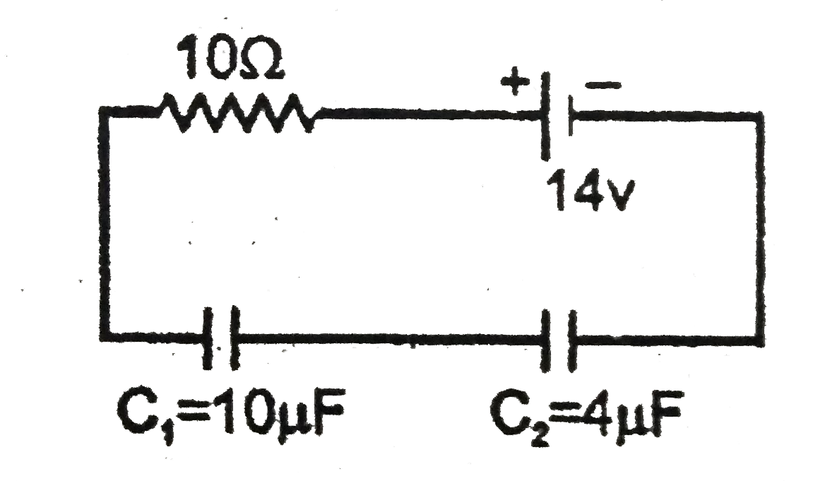
View SolutionThe circuit is in a steady state.
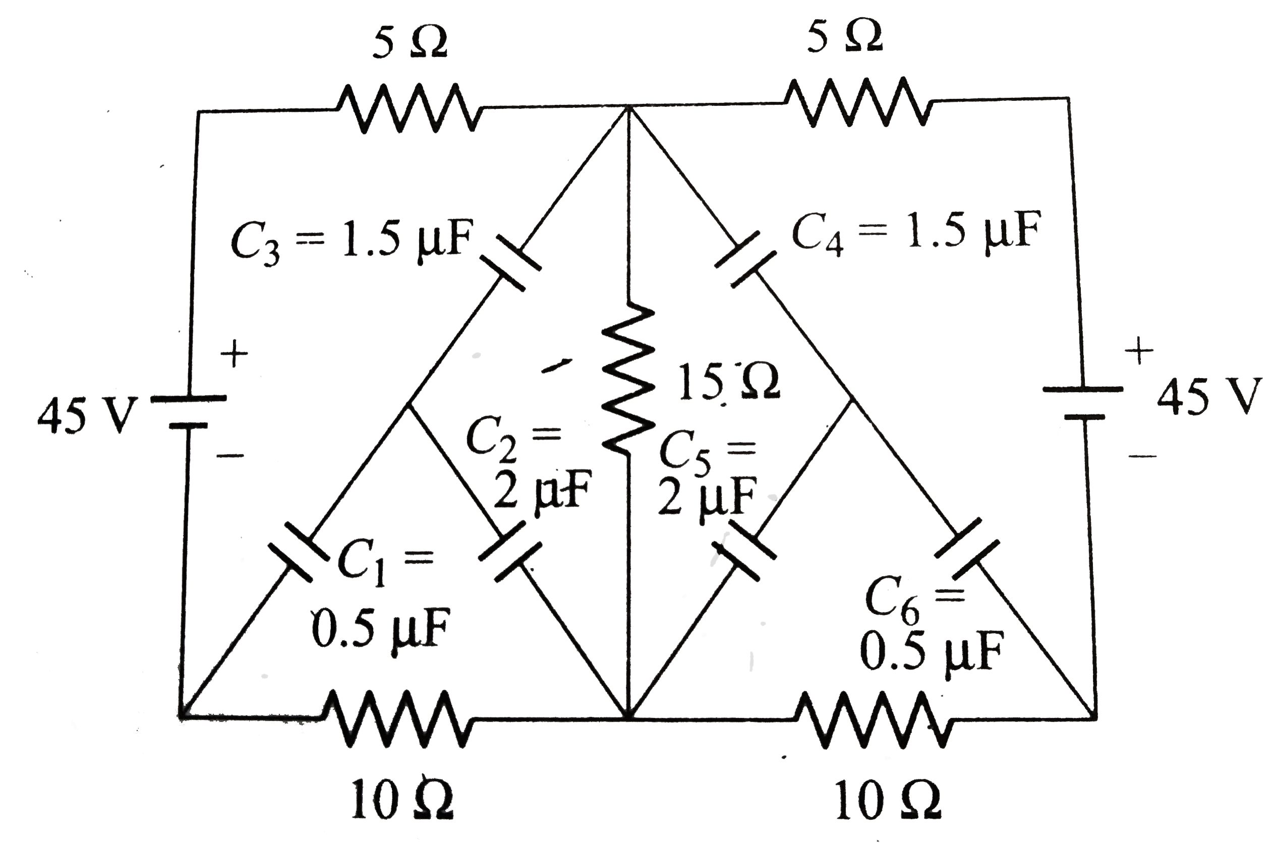
The charge in capacitor C1 is
View SolutionThe circuit is in a steady state.
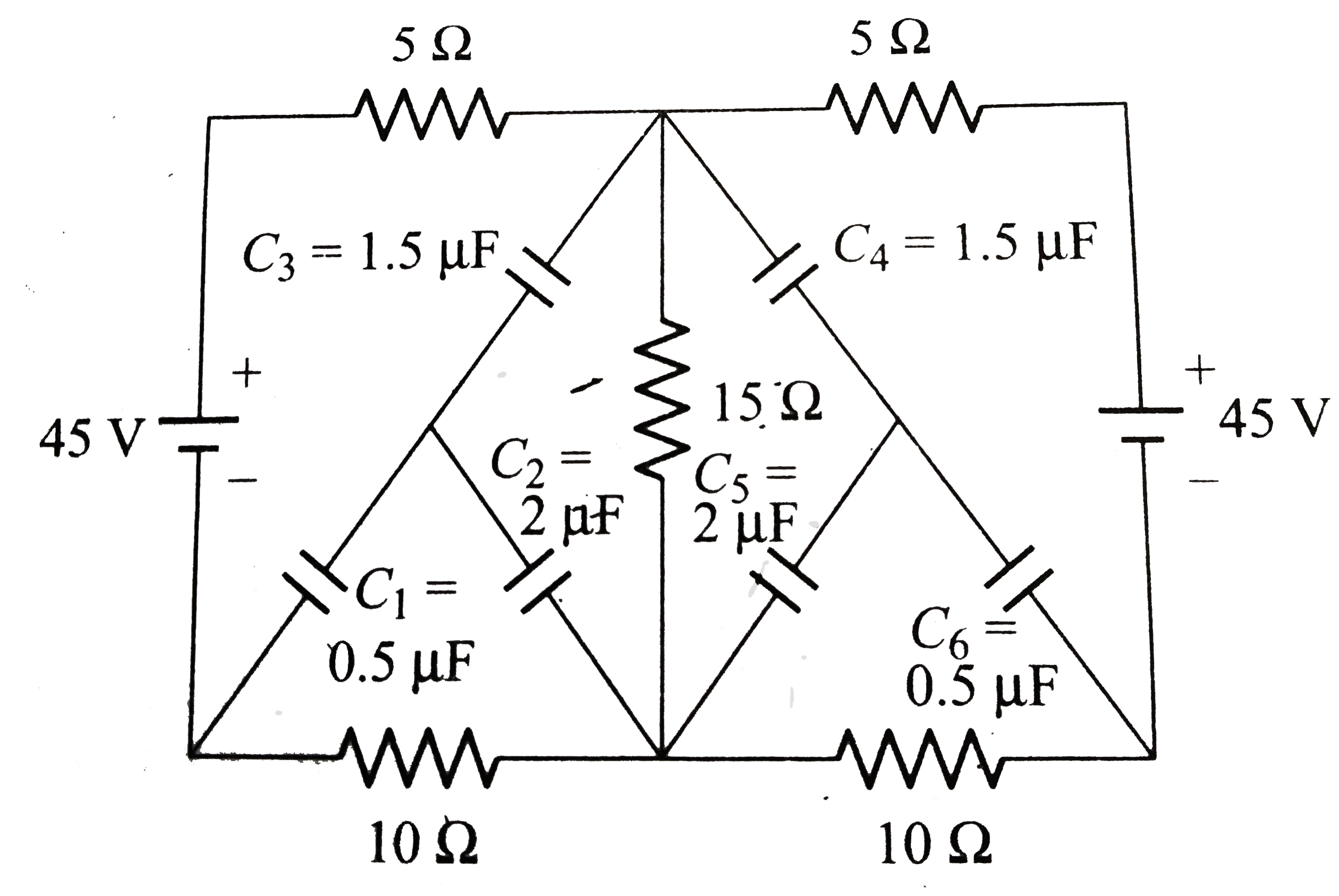
The charge in capacitor C2 is
View SolutionThe circuit is in a steady state.
The charge in capacitor C3 is
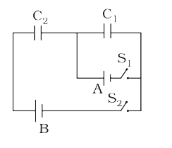
View SolutionIn the given circuit diagram, both capacitors are initially uncharged. The capacitance C1=2μFandC2=4μF, emf of battery A and B are 2V and 4V respectively.


View SolutionThe following two questions refer to the circuit shown. Assume that the capacitors are initially uncharged.
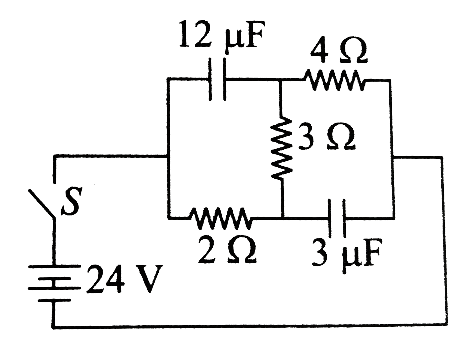
At time t = 0, the switch S in the circuit is closed. At that instant, what is the equivalent resistance of the circuit?
View SolutionThe following two questions refer to the circuit shown. Assume that the capacitors are initially uncharged.
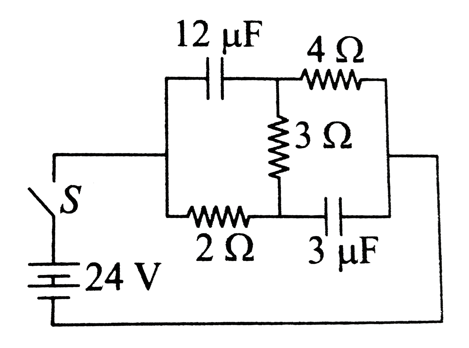
After the switch has been closed for a long time, how much charge is on the positive plate of the 3μF capacitor?
View SolutionFind the charge on capacitor in steady state.
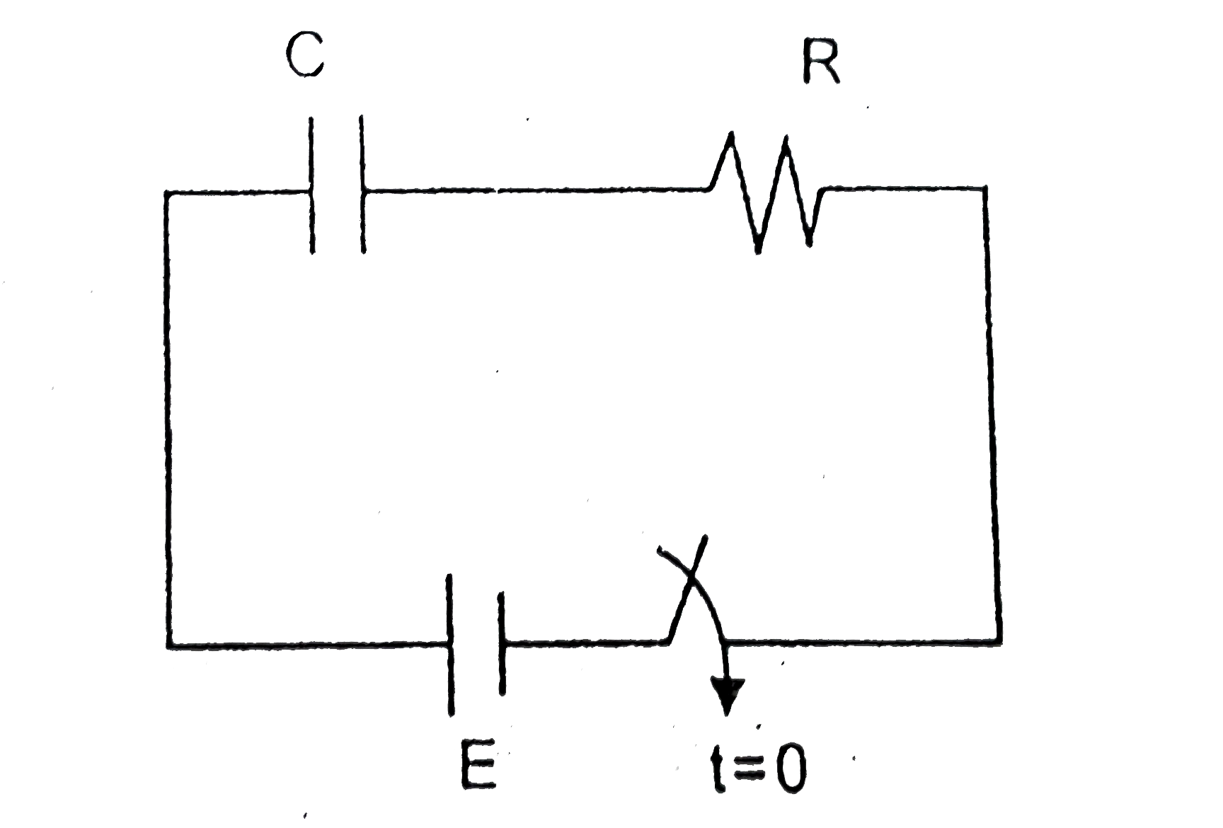
View SolutionIn the circuit shown key is closed at t=0 with capacitor initially uncharged.
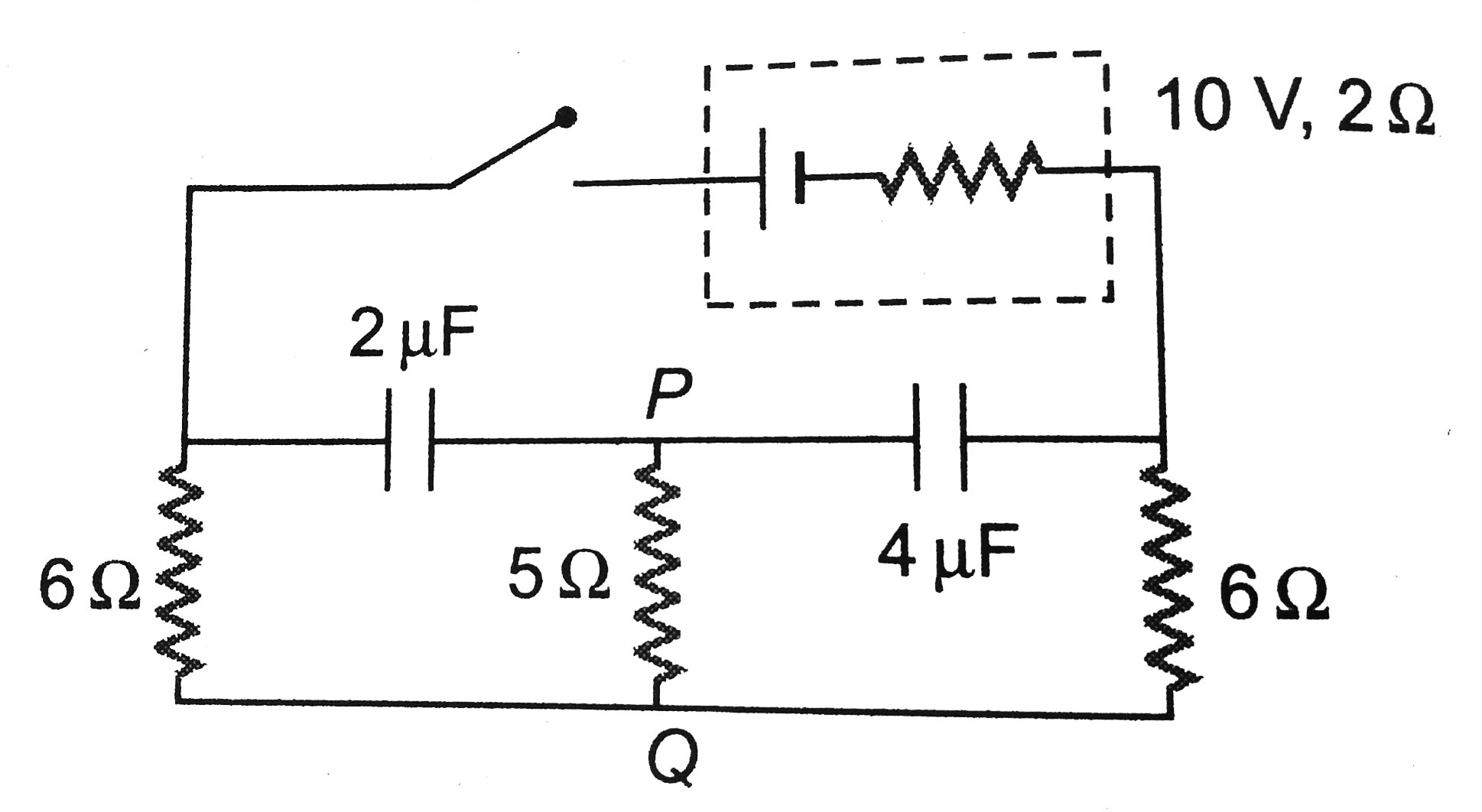
View SolutionIn the circuit shown in figure, the capacitors are initially uncharged. The current through resistor PQ just after closing the switch is
View Solution
