In the circuit shown all live resistors have the same value 200 ohms and each cell has an emf 3 volts. Find the open circuit voltage and the short circuit current for the terminals A and B.
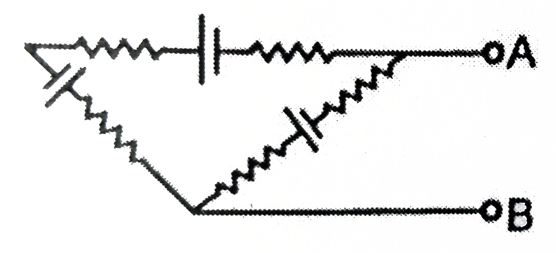
The correct Answer is:VB−VA=21/5=4.2v,I=35/2 mA =17.5 mA (B toA)
Step by step video & image solution for In the circuit shown all live resistors have the same value 200 ohms and each cell has an emf 3 volts. Find the open circuit voltage and the short circuit current for the terminals A and B. by Physics experts to help you in doubts & scoring excellent marks in Class 12 exams.
Updated on:21/07/2023Topper's Solved these Questions
- CURRENT ELECTRICITYBOOK - RESONANCE ENGLISHCHAPTER - CURRENT ELECTRICITYEXERCISE - Exercise-1 (Part-2)
47 Videos
- CURRENT ELECTRICITYBOOK - RESONANCE ENGLISHCHAPTER - CURRENT ELECTRICITYEXERCISE - Exercise-1 (Part-3)
2 Videos
- CURRENT ELECTRICITYBOOK - RESONANCE ENGLISHCHAPTER - CURRENT ELECTRICITYEXERCISE - Solued miscellaneous Prolblems
8 Videos
- COMMUNICATION SYSTEMSBOOK - RESONANCE ENGLISHCHAPTER - COMMUNICATION SYSTEMSEXERCISE - Exercise 3
13 Videos
- DAILY PRACTICE PROBLEMBOOK - RESONANCE ENGLISHCHAPTER - DAILY PRACTICE PROBLEMEXERCISE - DPP.No.71
1 Videos
Similar Questions
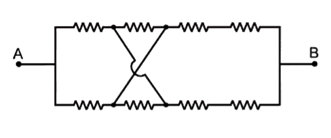
In the circuit shown, each resistor is of resistance R. the equivalent resistance between the terminals A and B is
View SolutionIn the figure shown, each resistor is of 20Ω and the cell has emf 10 volt with negligible internal resistance. Then rate of joule heating in the circuit is (in watts)
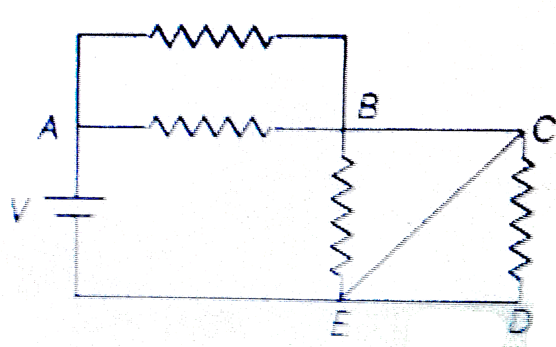
View SolutionIn the circuit diagram shown in find the current through the 1Ω resistor.

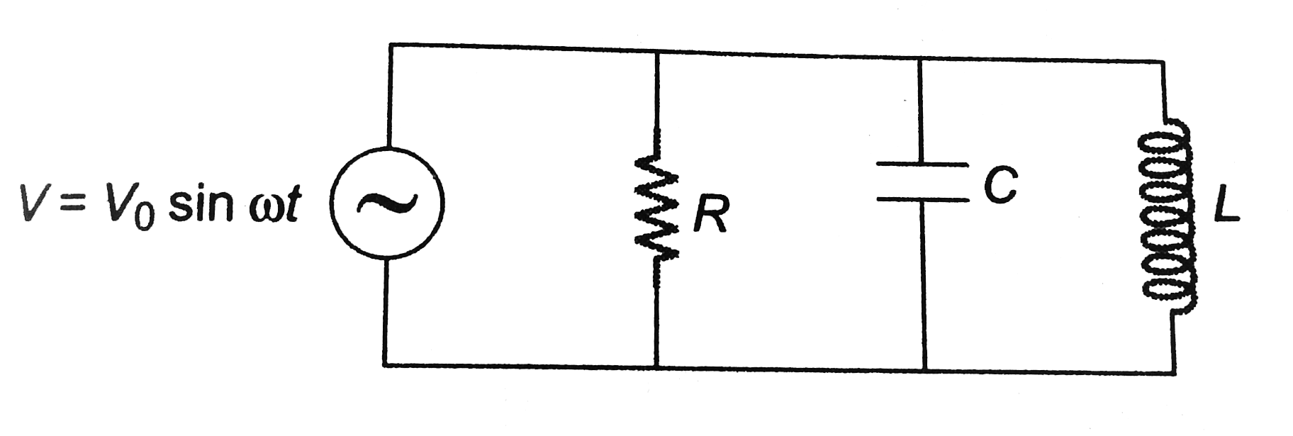
View SolutionFor the circuit shown in figureure, find the instaneous current through each element.
 .
.
View SolutionFor the circuit shown in figureure, find the instaneous current through each element.
 .
.
View SolutionFind the current in each resistor in the circuit as shown in fig.
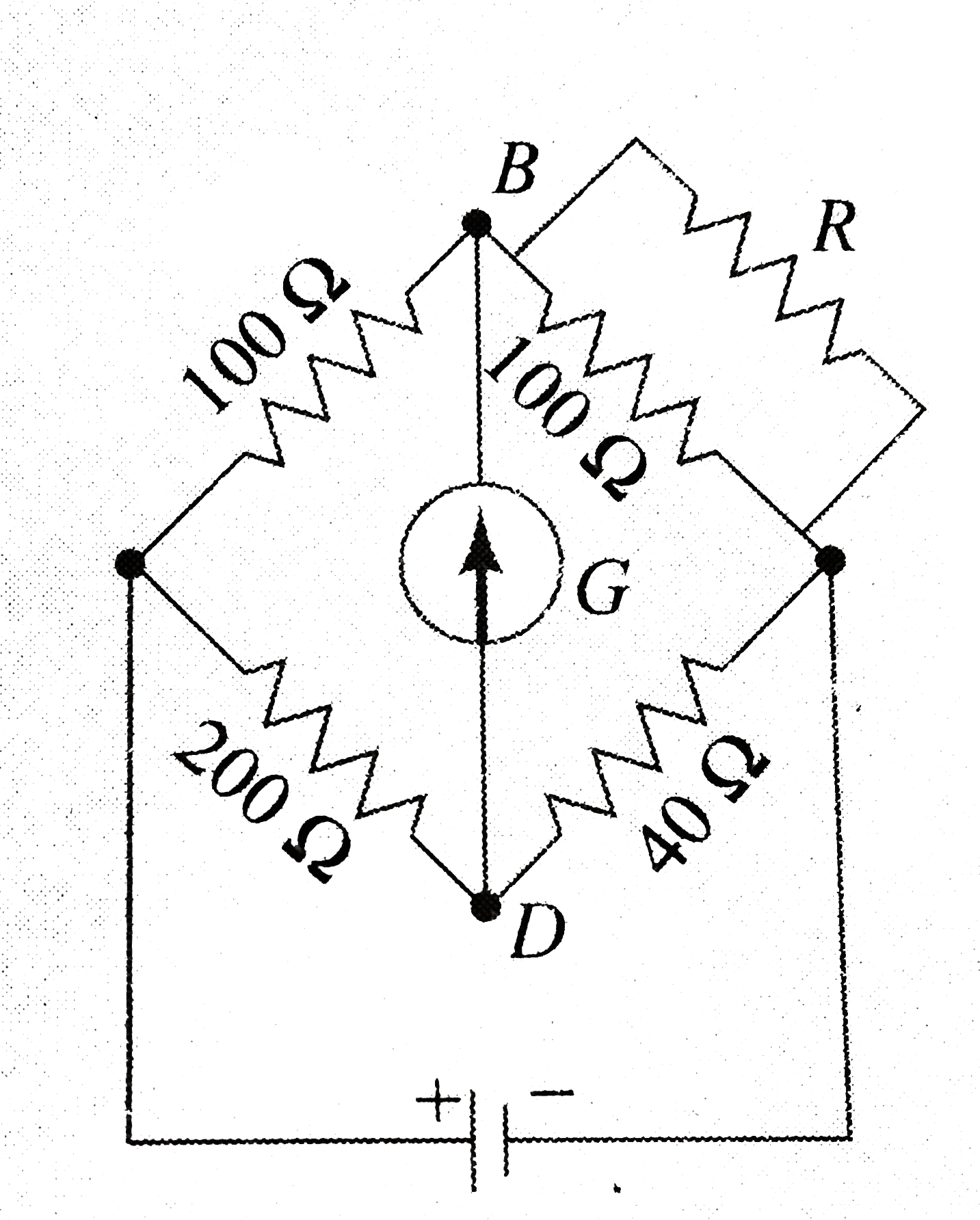
View SolutionThe capacitance of each capacitor as shown in the circuit is C. The effective capacitance of the circuit between terminals A and B is
View SolutionFor the circuit shown in figure, determine the voltage across 4Ω resistors in volt ?

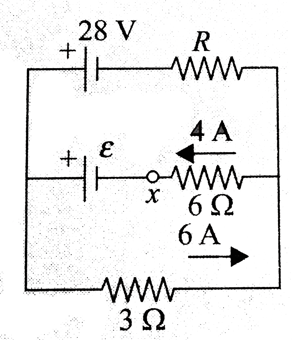
View SolutionIn the circuit shown in fig
a. find the current in resistor R
b. find the reistor R
c. find the the unkown emf ε
d. if the circuit is broken at point x,
what is the current in resistor R ?
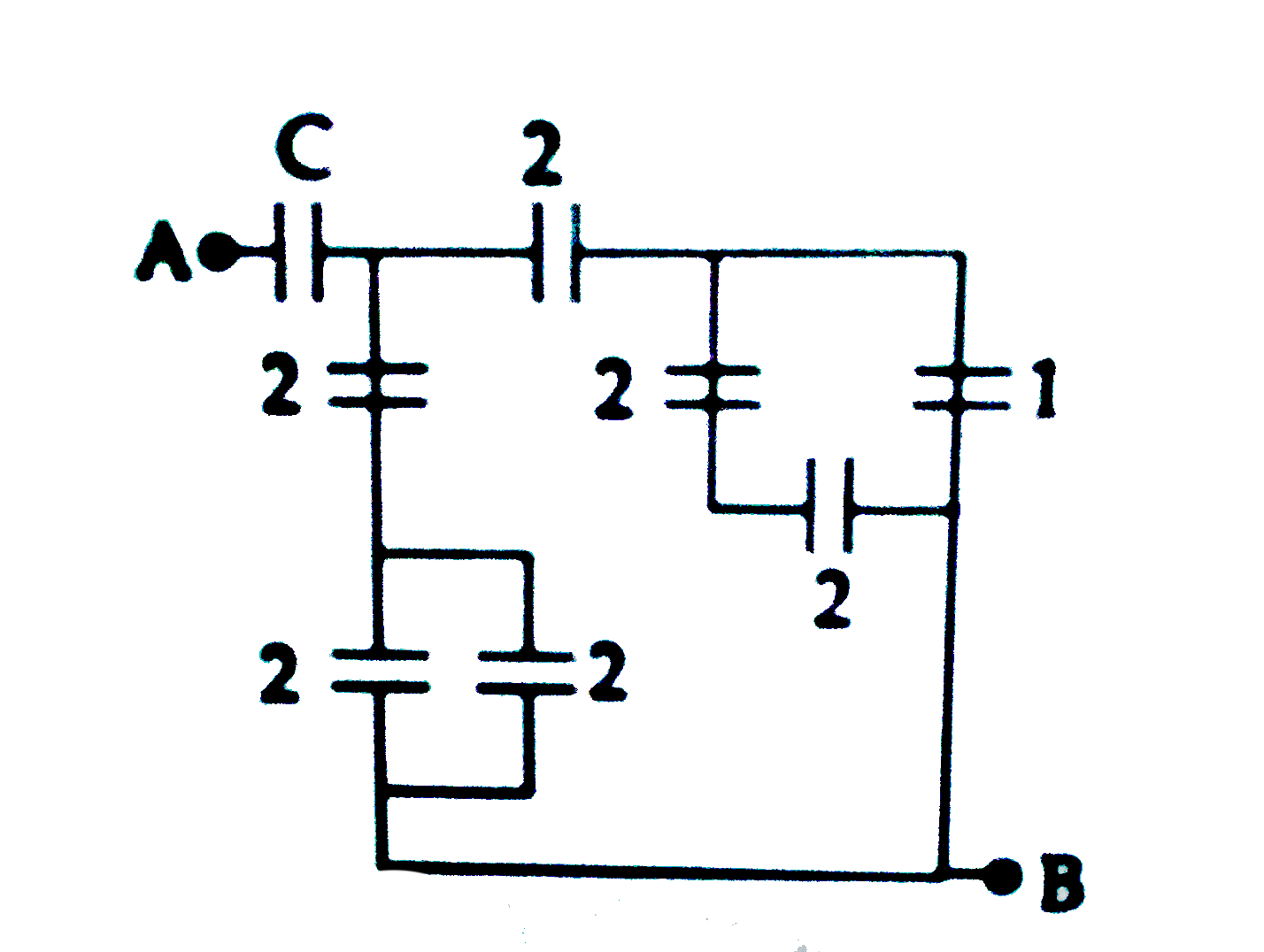
View SolutionIn the circuit shown, find C if the effective capacitance of the whole, circuit is to be 0.5μF. All values in the circuit are in μF.
View Solution
