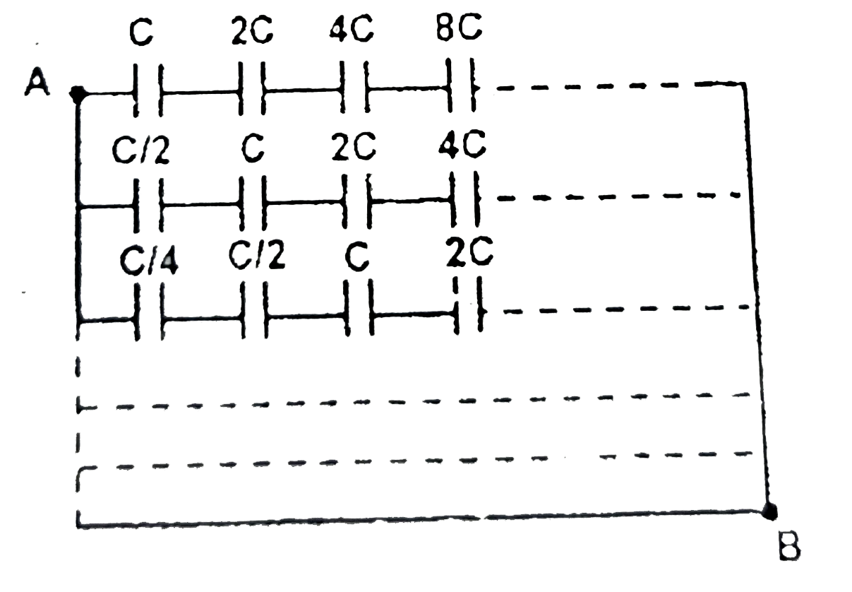
The capacitance of each capacitor as shown in the circuit is C. The effective capacitance of the circuit between terminals A and B is
4C
C/2
8C
2C
To find the effective capacitance Ceff of the given circuit with capacitors arranged in a specific manner, we can follow these steps:
1. Identify the Configuration:
The circuit consists of capacitors arranged in branches. Each branch has a different number of capacitors, and the capacitance of each capacitor decreases as we move down the branches. The first branch has 1 capacitor, the second has 2 capacitors, the third has 4 capacitors, and so on.
2. Define Capacitance Values:
- Let the capacitance of the first capacitor in the first branch be C1=C.
- For the second branch, we have two capacitors, each with C2=C2.
- For the third branch, we have four capacitors, each with C3=C4.
- For the fourth branch, we have eight capacitors, each with C4=C8.
- This pattern continues such that the n-th branch has 2n−1 capacitors, each with capacitance Cn=C2n−1.
3. Calculate Effective Capacitance:
The effective capacitance Ceff can be calculated by summing the contributions from each branch. The total effective capacitance can be expressed as:
Ceff=C1+C2+C3+C4+…
This can be written as:
Ceff=C+C2+C4+C8+…
4. Recognize the Series:
The series C+C2+C4+C8+… is a geometric series where:
- The first term a=C
- The common ratio r=12
5. Sum the Infinite Series:
The sum S of an infinite geometric series is given by the formula:
S=a1−r
Applying this to our series:
Ceff=C1−12=C12=2C
6. Final Result:
Therefore, the effective capacitance Ceff between terminals A and B is:
Ceff=2C
Conclusion:
The effective capacitance of the circuit between terminals A and B is 2C.
The circuit consists of capacitors arranged in branches. Each branch has a different number of capacitors, and the capacitance of each capacitor decreases as we move down the branches. The first branch has 1 capacitor, the second has 2 capacitors, the third has 4 capacitors, and so on.
- Let the capacitance of the first capacitor in the first branch be C1=C.
- For the second branch, we have two capacitors, each with C2=C2.
- For the third branch, we have four capacitors, each with C3=C4.
- For the fourth branch, we have eight capacitors, each with C4=C8.
- This pattern continues such that the n-th branch has 2n−1 capacitors, each with capacitance Cn=C2n−1.
The effective capacitance Ceff can be calculated by summing the contributions from each branch. The total effective capacitance can be expressed as:
Ceff=C1+C2+C3+C4+…
This can be written as:
Ceff=C+C2+C4+C8+…
The series C+C2+C4+C8+… is a geometric series where:
- The first term a=C
- The common ratio r=12
The sum S of an infinite geometric series is given by the formula:
S=a1−r
Applying this to our series:
Ceff=C1−12=C12=2C
Therefore, the effective capacitance Ceff between terminals A and B is:
Ceff=2C
The effective capacitance of the circuit between terminals A and B is 2C.
Topper's Solved these Questions
- TEST 1BOOK - AAKASH INSTITUTE ENGLISHCHAPTER - TEST 1EXERCISE - EXERCISE
21 Videos
- SYSTEM OF PARTICLES AND ROTATIONAL MOTIONBOOK - AAKASH INSTITUTE ENGLISHCHAPTER - SYSTEM OF PARTICLES AND ROTATIONAL MOTIONEXERCISE - Try Yourself
63 Videos
- TEST 2BOOK - AAKASH INSTITUTE ENGLISHCHAPTER - TEST 2EXERCISE - Exercise
308 Videos
Similar Questions
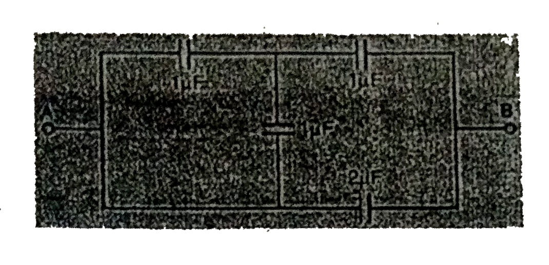
Find the equivaent capacitance of the circuit between point A and B.

View SolutionThe equivalent capacitance of the circuit shown, between points A and B will be-
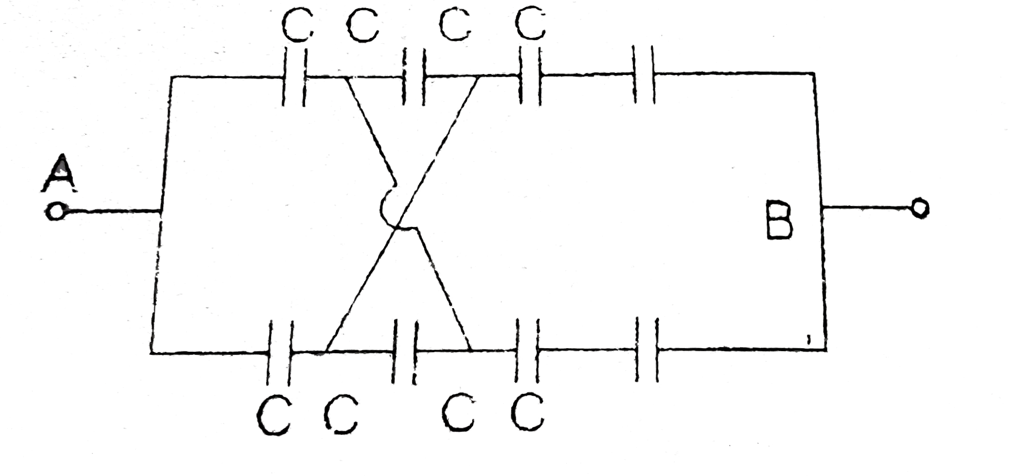
View SolutionFind the equivalent capacitance between terminals A and B.
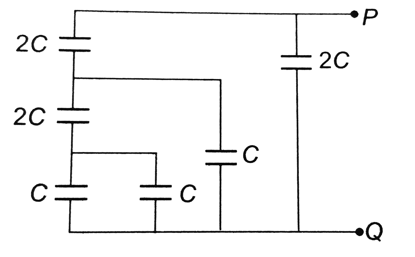
View SolutionThe resultant capacitance of given circuit is
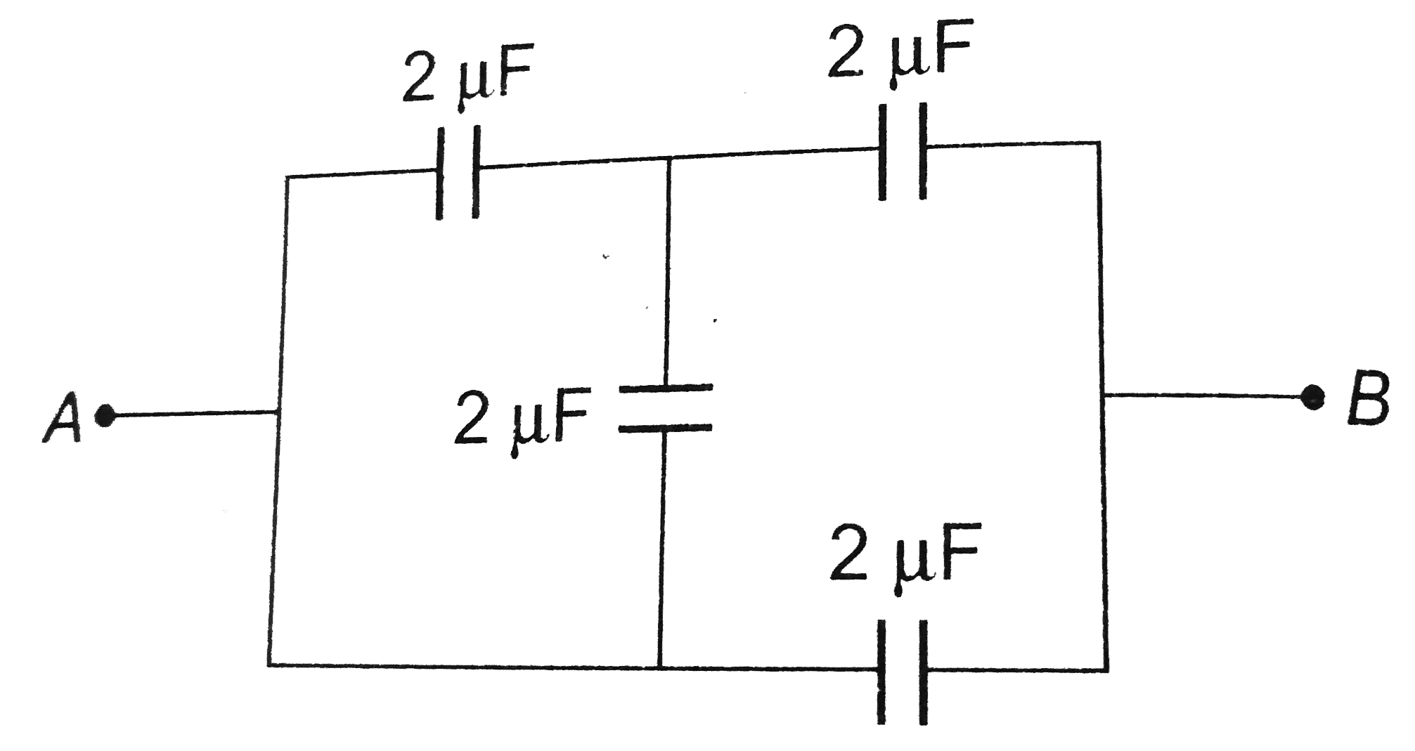
View SolutionFour capacitors are connected in a circuit as shown in the figure. The effective capacitance in μF between points A and B will be
View SolutionSix identical capacitors are connected as shown in figure. Capacitance of each capacitors is 5μF The effective capacitance between point A and B is
View SolutionConsider an infinite matrix of capacitors as shown in the figure.
The effective capacitance between point A and B will be
View SolutionThree capacitors C1=3μF,C2=6μFandC3=10μF are connected to a 50 V battery as shown in the figure below:
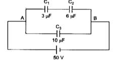
Calculate :
The equivalent capacitance of the circuit between points A and B.
View SolutionIn the circuit as shown in the figure the effective capacitance between A and B is
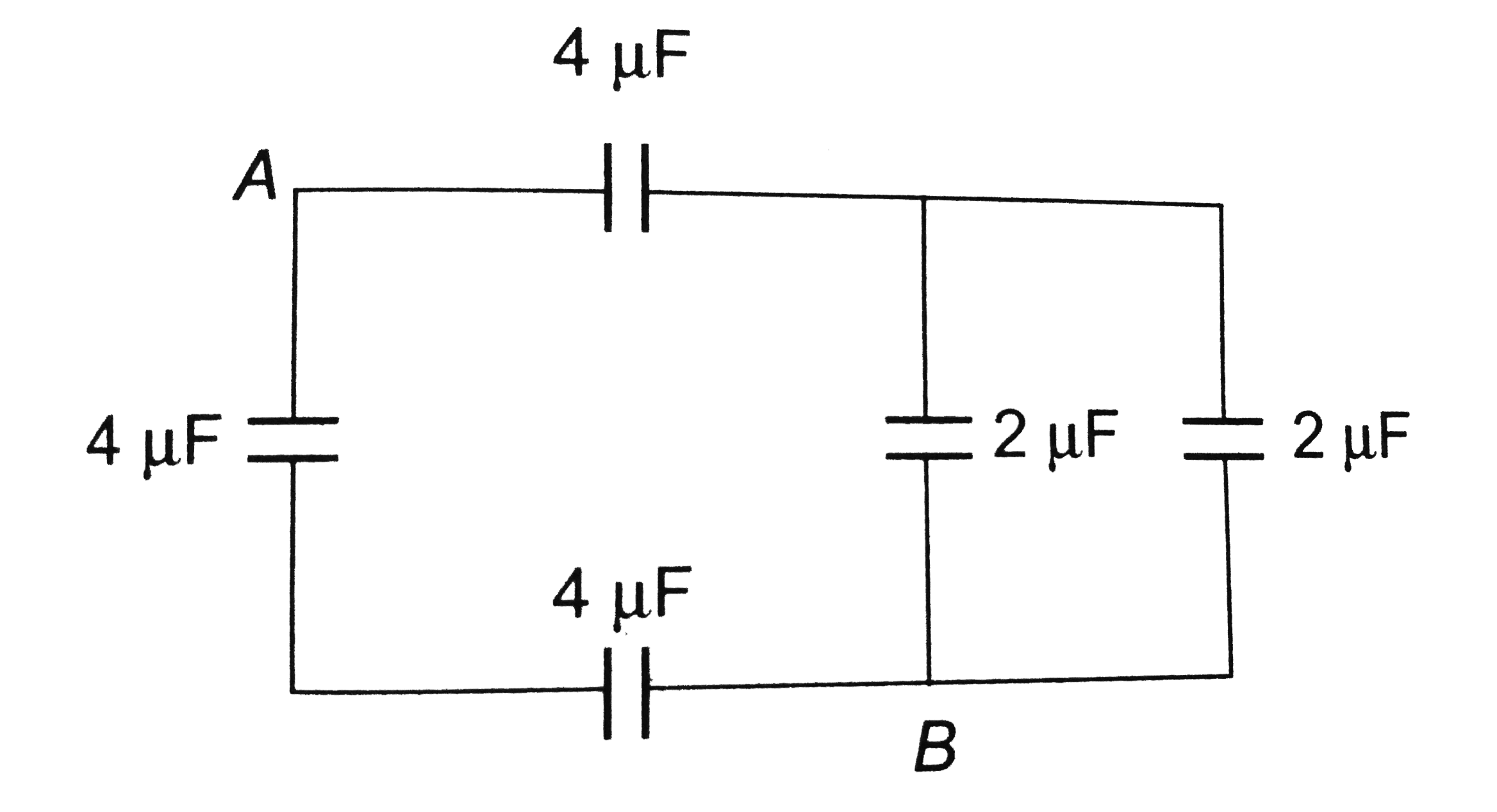
View SolutionIn the circuit as shown in the figure the effective capacitance between A and B is

View Solution

