In the circuit given in the figure, both batteries are ideal . Emf of battery 1 has a fixed value, but emf of battery 2 can be varied between . The graph gives the currents through the two batteries as a function of but are not marked as which plot corresponds to which battery. But for both plots, current is assumed to be negative when the direction of the current through the battery is opposite to the direction of that battery's emf (direction of emf is from negative to positive.)
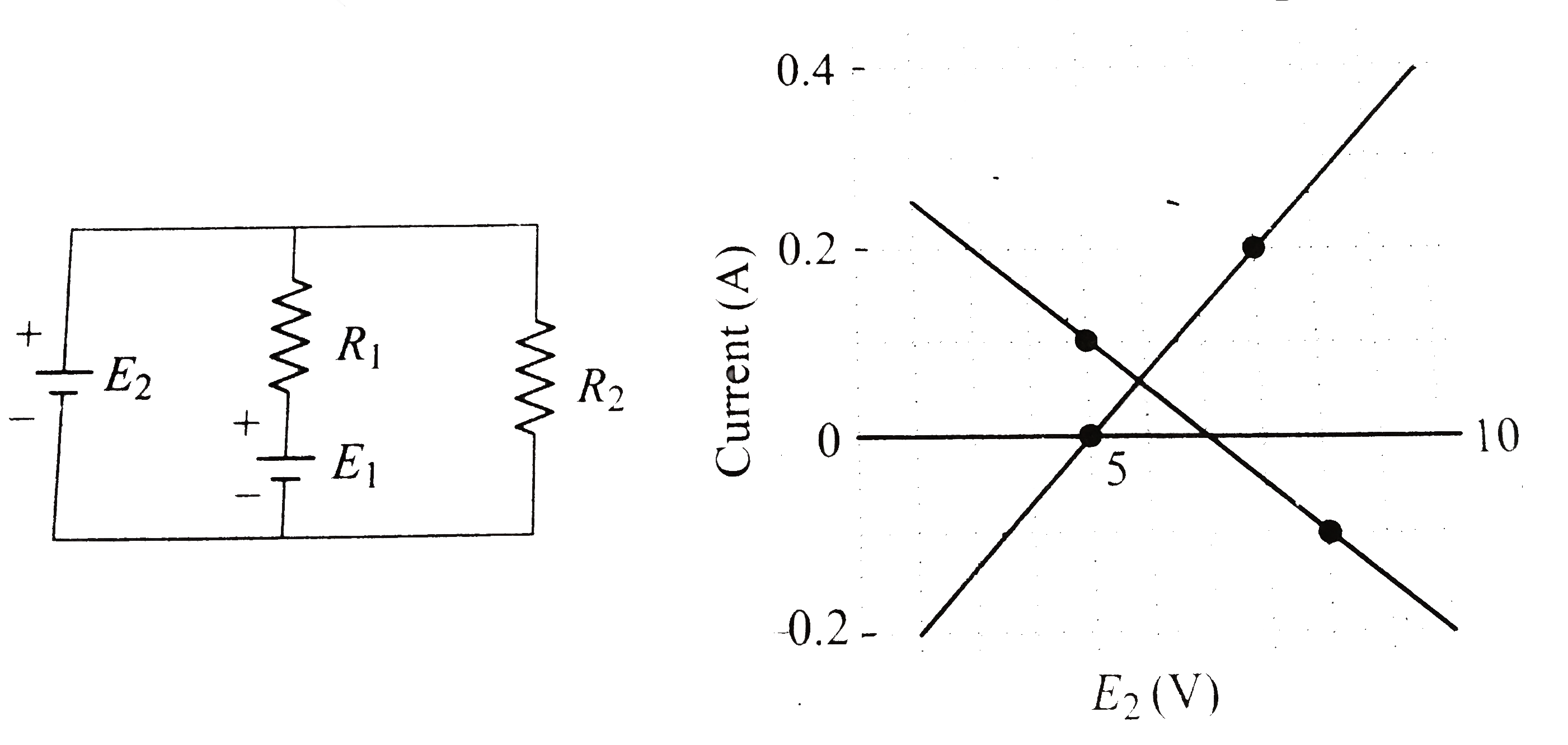 ,
,
The resistance has value
The correct Answer is:B
Step by step video & image solution for In the circuit given in the figure, both batteries are ideal . Emf E_1 of battery 1 has a fixed value, but emf E_2 of battery 2 can be varied between 1.0V and 10.0 V . The graph gives the currents through the two batteries as a function of E_2 but are not marked as which plot corresponds to which battery. But for both plots, current is assumed to be negative when the direction of the current through the battery is opposite to the direction of that battery's emf (direction of emf is from negative to positive.) , The resistance R_1 has value by Physics experts to help you in doubts & scoring excellent marks in Class 12 exams.
Updated on:21/07/2023Topper's Solved these Questions
- CURRENT ELECTRICITYBOOK - RESONANCE ENGLISHCHAPTER - CURRENT ELECTRICITYEXERCISE - Exrcies-3(PART-1)
22 Videos
- CURRENT ELECTRICITYBOOK - RESONANCE ENGLISHCHAPTER - CURRENT ELECTRICITYEXERCISE - Exrcies-3(PART-2)
23 Videos
- CURRENT ELECTRICITYBOOK - RESONANCE ENGLISHCHAPTER - CURRENT ELECTRICITYEXERCISE - Exercise-2 (Part-3)
22 Videos
- COMMUNICATION SYSTEMSBOOK - RESONANCE ENGLISHCHAPTER - COMMUNICATION SYSTEMSEXERCISE - Exercise 3
13 Videos
- DAILY PRACTICE PROBLEMBOOK - RESONANCE ENGLISHCHAPTER - DAILY PRACTICE PROBLEMEXERCISE - DPP.No.71
1 Videos
Similar Questions
In the circuit given in the figure, both batteries are ideal . Emf E1 of battery 1 has a fixed value, but emf E2 of battery 2 can be varied between 1.0Vand10.0V . The graph gives the currents through the two batteries as a function of E2 but are not marked as which plot corresponds to which battery. But for both plots, current is assumed to be negative when the direction of the current through the battery is opposite to the direction of that battery's emf (direction of emf is from negative to positive.)
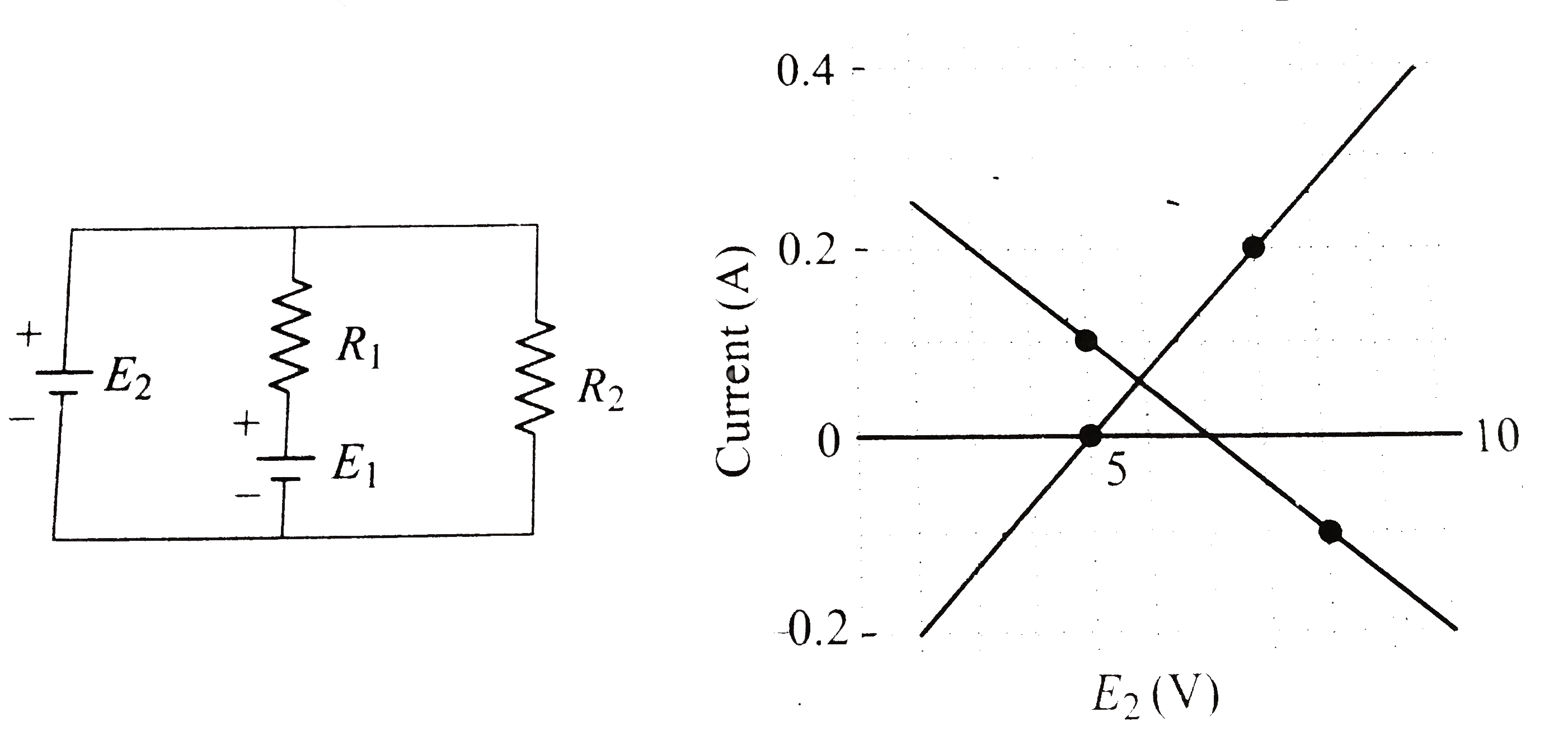
The value of emf E1 is
View SolutionIn the circuit given in the figure, both batteries are ideal . Emf E1 of battery 1 has a fixed value, but emf E2 of battery 2 can be varied between 1.0Vand10.0V . The graph gives the currents through the two batteries as a function of E2 but are not marked as which plot corresponds to which battery. But for both plots, current is assumed to be negative when the direction of the current through the battery is opposite to the direction of that battery's emf (direction of emf is from negative to positive.)
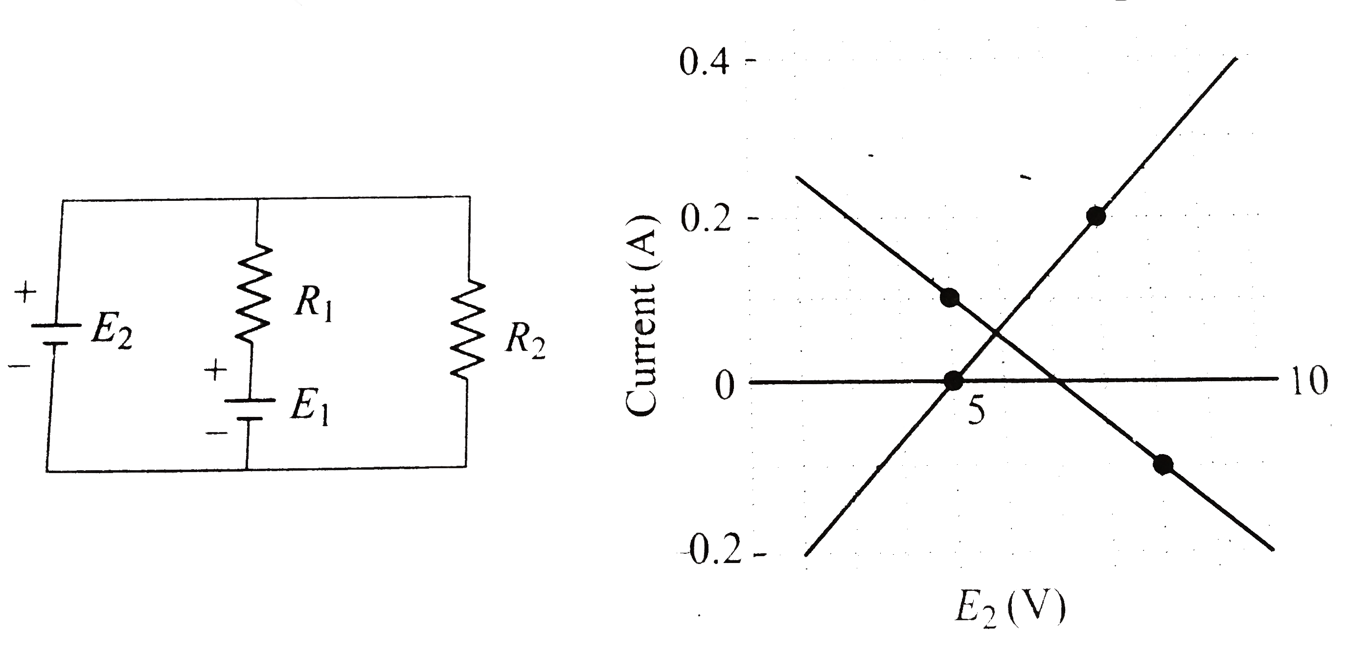 ,
,
The resistance R2 is equal to
View SolutionIn the given circuit,
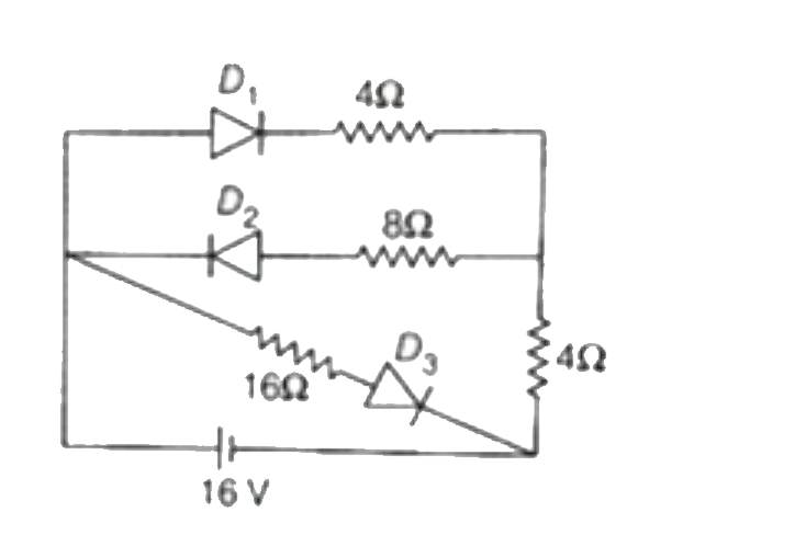
the current through the battery is
View Solution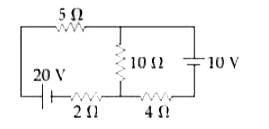
In the figure shown , the current in the 10 V battery is close to :
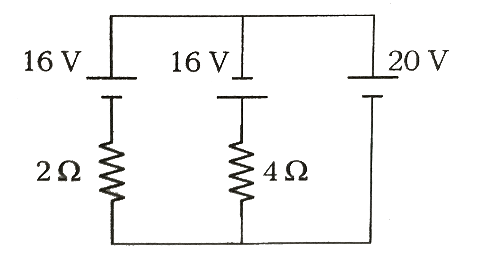
View SolutionIn the given figure, the current through the 20 V battery is
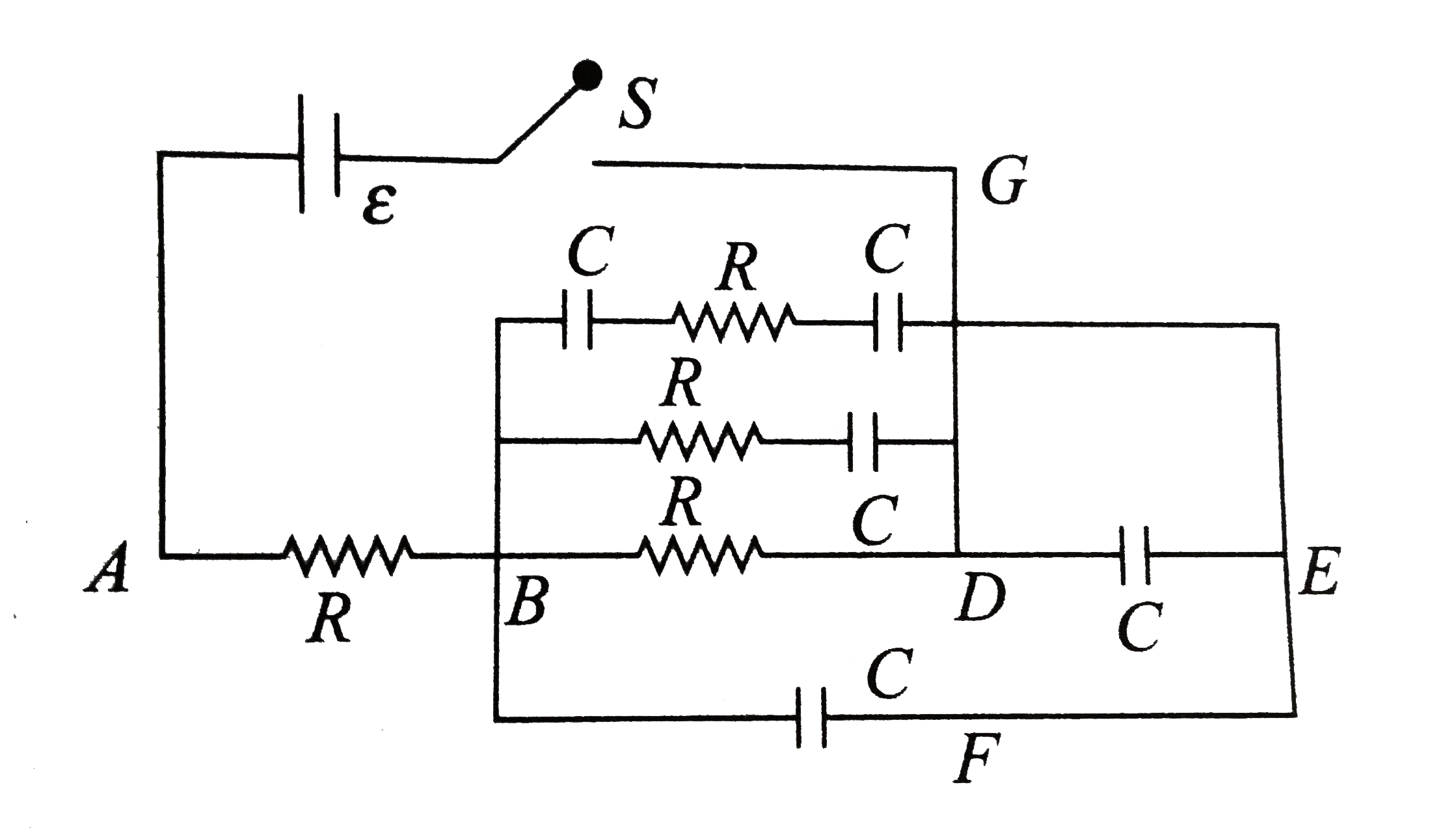
View SolutionCurrent through the battery in the circuit shown in the figure
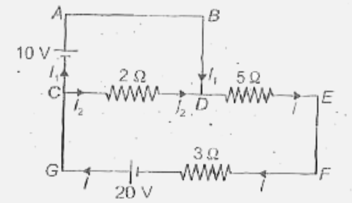
View SolutionIn the network shown in given figure the current l1 through the 10 V battery .
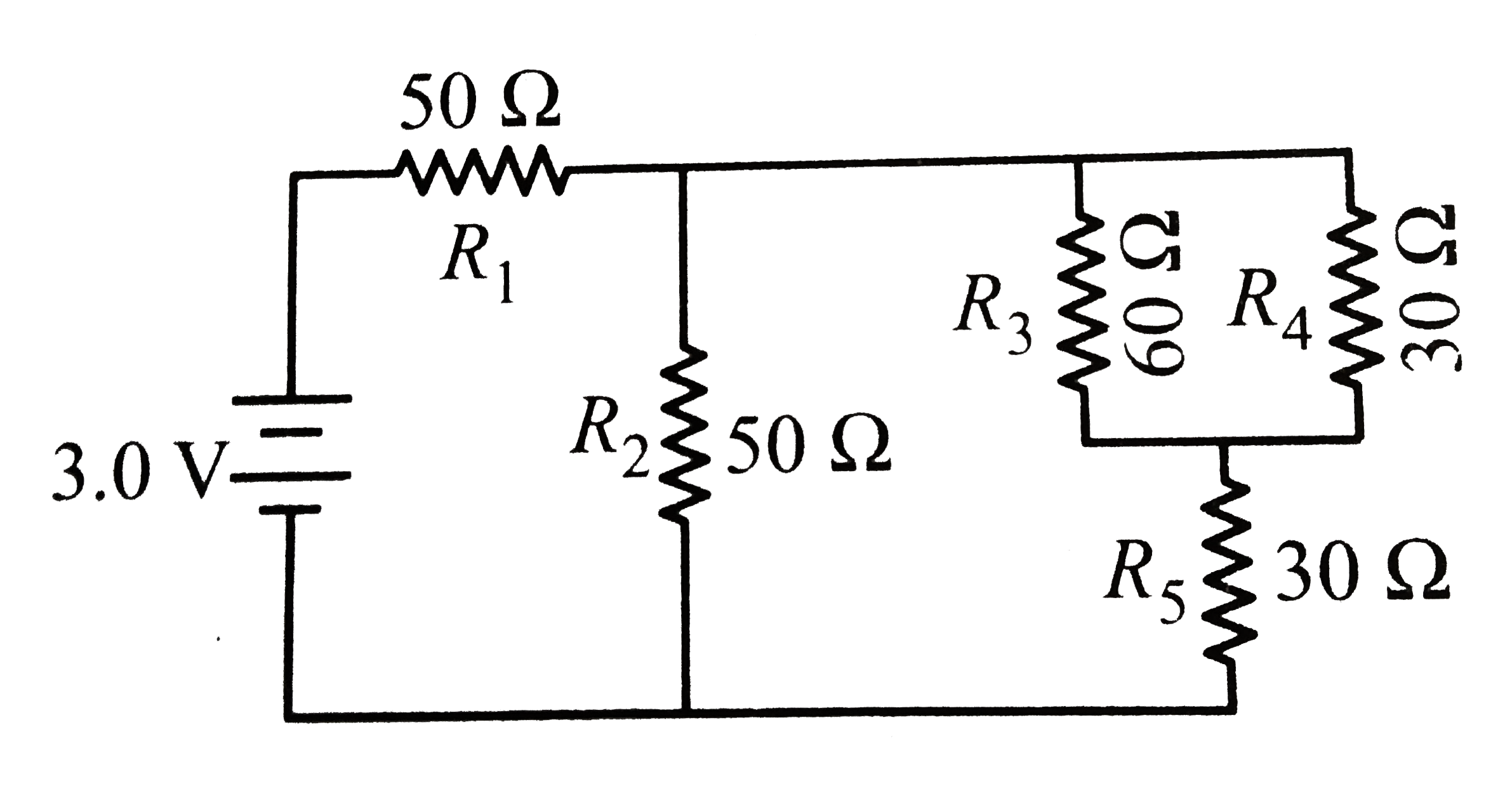
View SolutionIn the circuit shown, the resistances are given in ohms and the battery is assumed ideal with emf equal to 3.0 V.
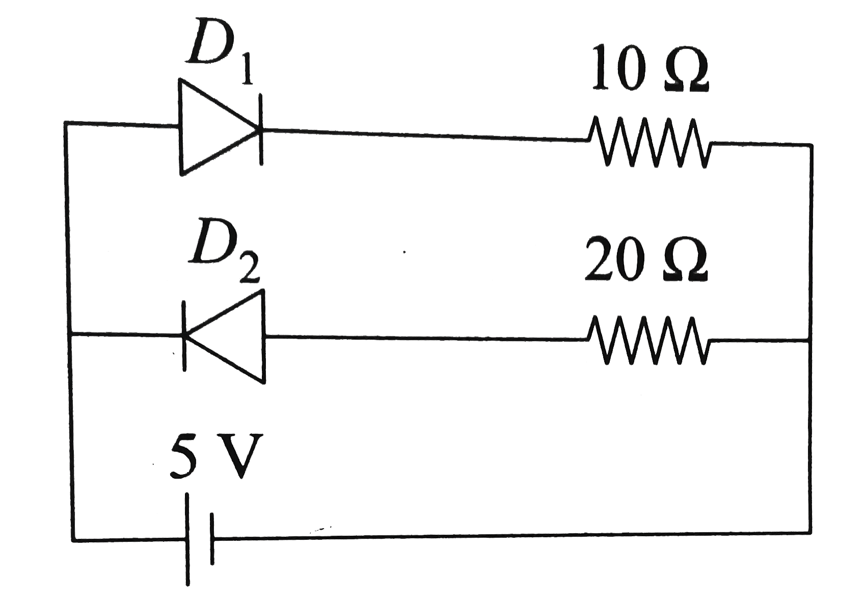
View SolutionTwo ideal diodes are connected to a battery as shown in the circuit. The current supplied by the battery is
View SolutionTwo ideal diodes are connected to a battery as shown in the circuit. The current supplied by the battery is
View Solution
