Electrons are emitted by a hot filament and are accelerated by an electric field as shown in figure .The two stops at the left ensure that the electron beam has a uniform cross-section.
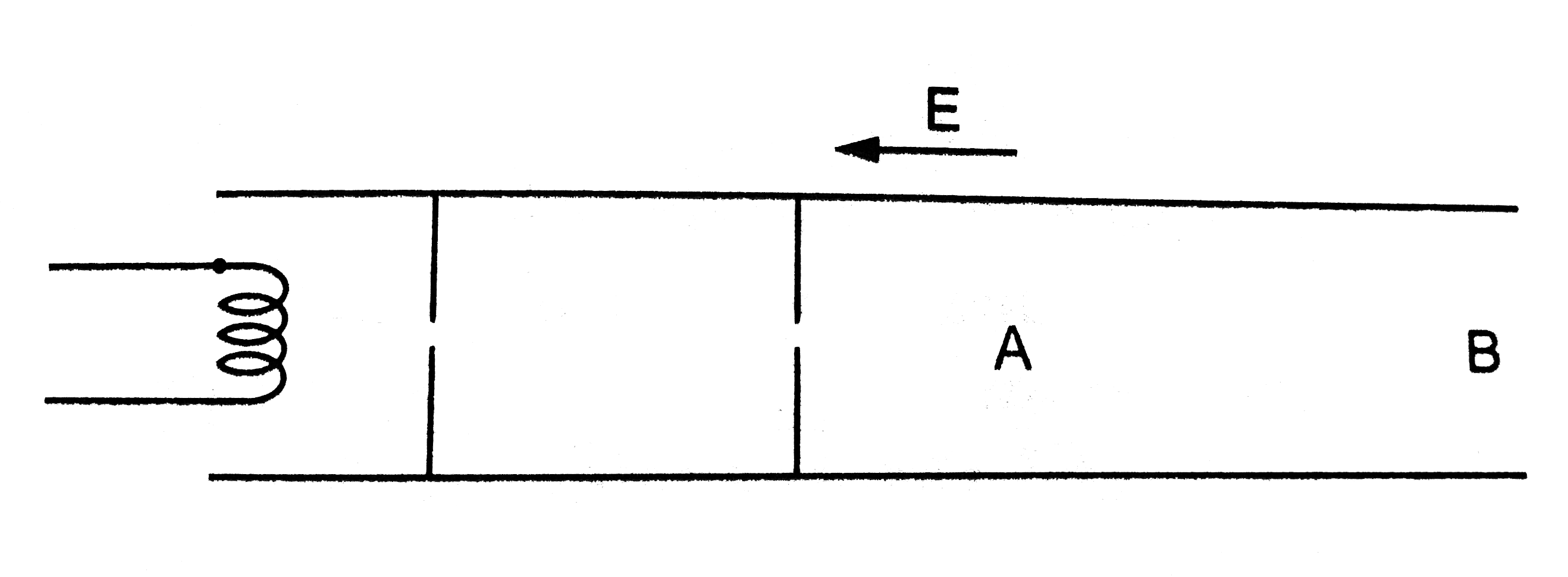
Linear momentum of electron increases from A to B.
The electric current is from right to left
The magnitude of the current is same at A and B.
The current density is same at A and B.
The correct Answer is:A, B, C, D
Step by step video & image solution for Electrons are emitted by a hot filament and are accelerated by an electric field as shown in figure .The two stops at the left ensure that the electron beam has a uniform cross-section. by Physics experts to help you in doubts & scoring excellent marks in Class 12 exams.
Updated on:21/07/2023Topper's Solved these Questions
- CURRENT ELECTRICITYBOOK - RESONANCE ENGLISHCHAPTER - CURRENT ELECTRICITYEXERCISE - Exercise-2 (Part-4)
12 Videos
- CURRENT ELECTRICITYBOOK - RESONANCE ENGLISHCHAPTER - CURRENT ELECTRICITYEXERCISE - Exrcies-3(PART-1)
22 Videos
- CURRENT ELECTRICITYBOOK - RESONANCE ENGLISHCHAPTER - CURRENT ELECTRICITYEXERCISE - Exercise-2 (Part-2)
16 Videos
- COMMUNICATION SYSTEMSBOOK - RESONANCE ENGLISHCHAPTER - COMMUNICATION SYSTEMSEXERCISE - Exercise 3
13 Videos
- DAILY PRACTICE PROBLEMBOOK - RESONANCE ENGLISHCHAPTER - DAILY PRACTICE PROBLEMEXERCISE - DPP.No.71
1 Videos
Similar Questions
In the uniform electric field shown in figure, find

View SolutionElectron are emited from an electron gun at almost zero velocity and are accelerated by an electric field E through a distance of 1.0m The electron are now scatteared by an atomic hydrogen sample in ground state what should be the minimum value of E so that red light of wavelength 656.5nm may be emitted by the hydrogen?
View SolutionA proton and an electron are placed in a uniform electric field.
View SolutionFollowing experiment was performed by J.J. Thomson in order to measure ratio of charge e and mass m of electron.
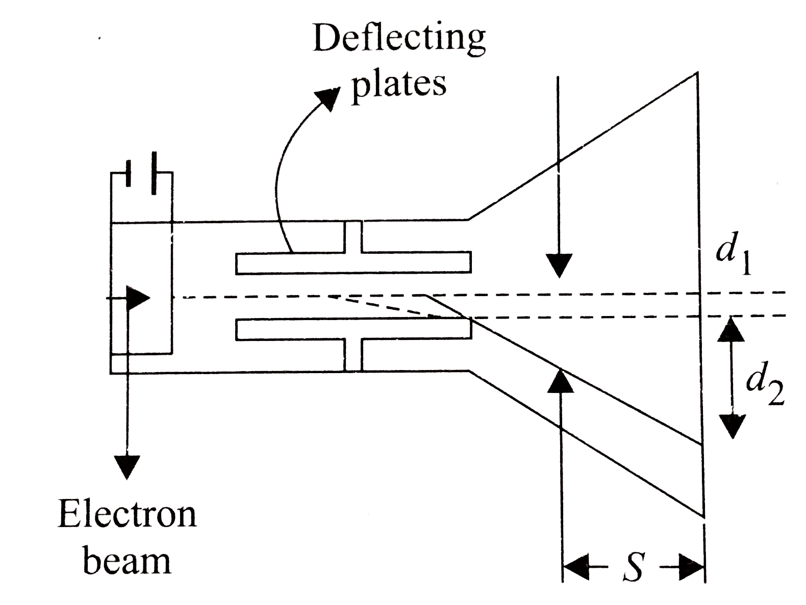
Electrons emitted from a hot filament are accelerated by a potential difference V. As the electrons pass through deflecting plates, they encounter both electric and magnetic fields. the entire region in which electrons leave the plates they enters a field free region that extends to fluorescent screen. The entire region in which electrons travel is evacuated.
Firstly, electric and magnetic fields were made zero and position of undeflected electron beam on the screen was noted. The electric field was turned on and resulting deflection was noted. Deflection is given by d1=eEL22mV2 where L = length of deflecting plate and v = speed of electron.
In second part of experiment, magnetic field was adjusted so as to exactly cancel the electric force leaving the electron beam undeflected. This gives eE=evB. Using expression for d1 we can find out em=2d1EB2L2
A beam of electron with velocity 3×10⁷ms−1 is deflected 2 mm while passing through 10 cm in an electric field of 1800V/m perpendicular to its path. e/m for electron is
View SolutionFollowing experiment was performed by J.J. Thomson in order to measure ratio of charge e and mass m of electron.
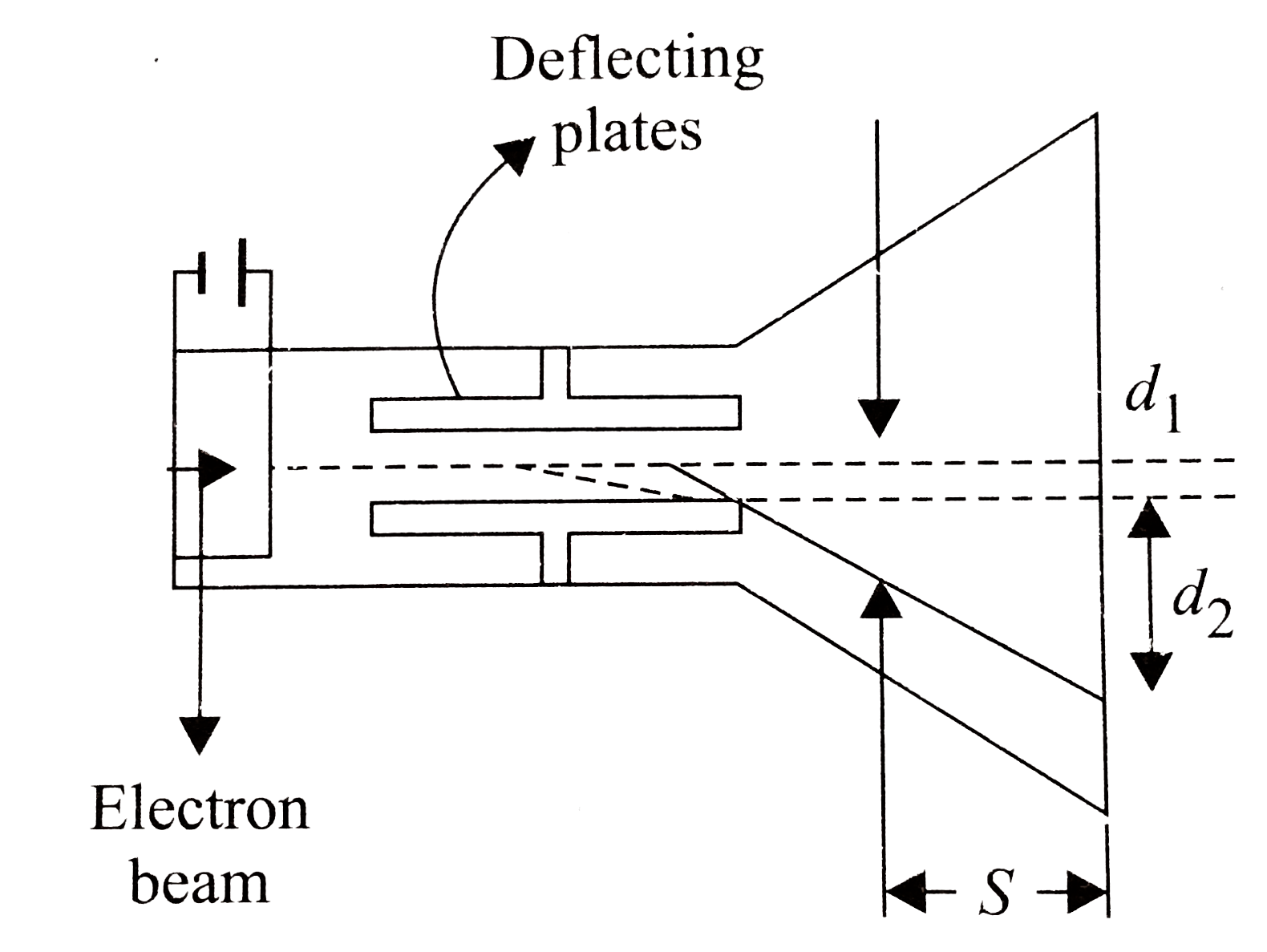
Electrons emitted from a hot filament are accelerated by a potential difference V. As the electrons pass through deflecting plates, they encounter both electric and magnetic fields. the entire region in which electrons leave the plates they enters a field free region that extends to fluorescent screen. The entire region in which electrons travel is evacuated.
Firstly, electric and magnetic fields were made zero and position of undeflected electron beam on the screen was noted. The electric field was turned on and resulting deflection was noted. Deflection is given by d1=eEL22mV2 where L = length of deflecting plate and v = speed of electron.
In second part of experiment, magnetic field was adjusted so as to exactly cancel the electric force leaving the electron beam undeflected. This gives eE = evB. Using expression for d1 we can find out em=2d1EB2L2
If the electron is deflected downward when only electric field is turned on, in what direction do the electric and magnetic fields point in second part of experiment
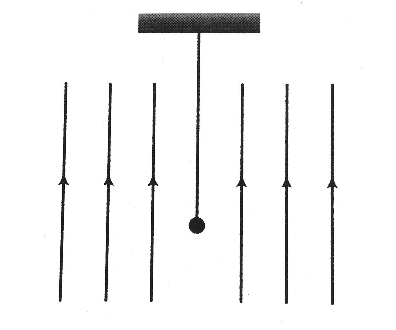
View SolutionA neutral pendulum oscillates in a uniform electric field as shown in figure. If a positive charge is given to the pendulum, then its time period
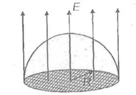
View SolutionA hemispherical surface of radius R is kept in a uniform electric field E as shown in figure. The flux through the curved surface is
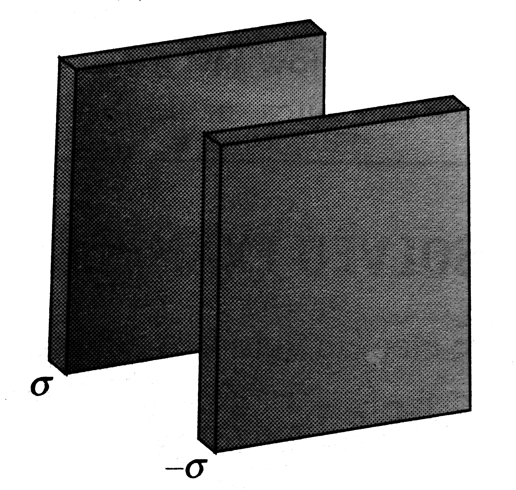
View SolutionTwo infinite, non-conducting sheets of charge are parallel to each other, as shown in figure. The sheet on the left has a uniform surface charge density σ, and the one on the right has a uniform charge density −σ. Calculate the electric field at points (a) to the left of, (b) in between, and (c) to the right of the two sheets.
View SolutionThe ends of a long bar are maintained at different temperatures and there is no loss of heat from the sides of the bar due to conduction or radiation. The graph of temperature against distance of the bar when it has attained steady state is shown here. The graph shows (i) the temperature gradient is not uniform.
(ii) the bar has uniform cross-sectional area.
(iii) the cross-sectional area of the bar increases as the distance from the hot end increases.
(iv) the cross-sectional area of the bar becreases as the distance from the hot end increases
View SolutionAn electric dipole is placed in uniform electric field as shown in the figure. The dipole is slightly rotated about its centre and released. Select the correct statement(s).
View Solution
