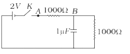
In the adjoining circuit, the capacitor is initially uncharged. The current through the resistor AB immediately after the key K is pressed is __________ mA.
The correct Answer is:2
When a capacitor is uncharged, the potential difference across it must be zero. So, no current can flow initially through the resistance connected in parallel with the capacitor
i=21000=0.02A=2mA
Topper's Solved these Questions
- CAPACITORSBOOK - VMC MODULES ENGLISHCHAPTER - CAPACITORSEXERCISE - JEE Main (Archive) LEVEL-1
36 Videos
- CAPACITORSBOOK - VMC MODULES ENGLISHCHAPTER - CAPACITORSEXERCISE - JEE Advance ( Archive ) LEVEL 2
1 Videos
- CAPACITORSBOOK - VMC MODULES ENGLISHCHAPTER - CAPACITORSEXERCISE - LEVEL 1 (MCQs)
60 Videos
- BASIC MATHEMATICS & VECTORSBOOK - VMC MODULES ENGLISHCHAPTER - BASIC MATHEMATICS & VECTORSEXERCISE - Impeccable
50 Videos
- CURRENT ELECTRICITYBOOK - VMC MODULES ENGLISHCHAPTER - CURRENT ELECTRICITYEXERCISE - IN-CHAPTER EXERCISE-F
10 Videos
Similar Questions
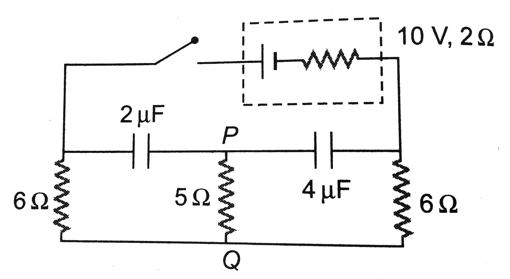
In the circuit shown in figure, the capacitors are initially uncharged. The current through resistor PQ just after closing the switch is
View Solution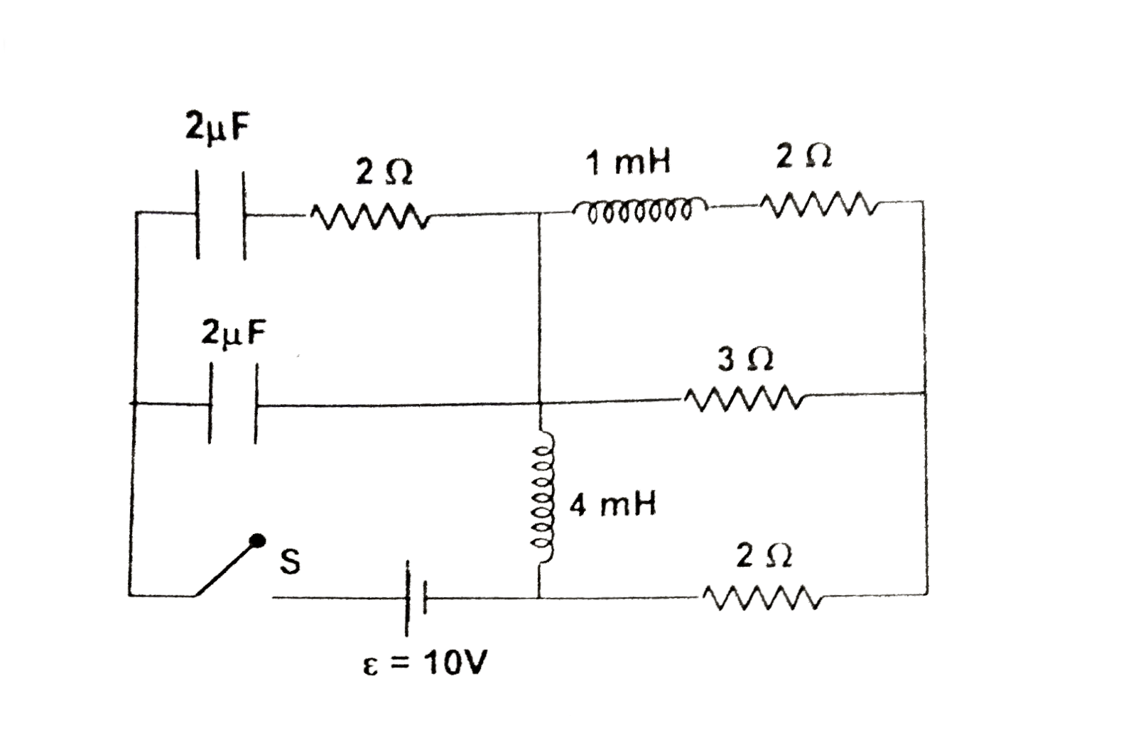
In the circuit shown, all the capacitors are initially uncharged. The current through the battery just after closing the switch 'S' is
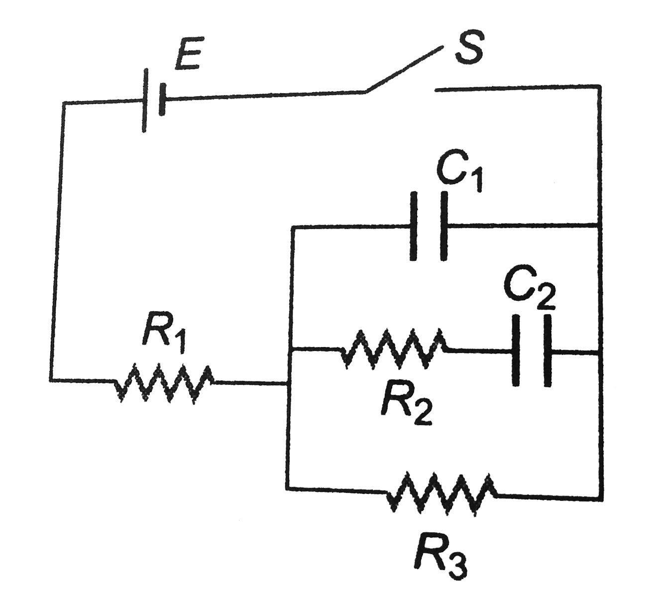
View SolutionIn the circuit diagram the current through the battery immediately after the switch S is closed is
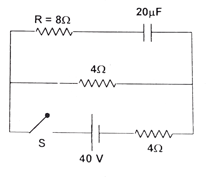
View SolutionIn the circuit shown, the switch 'S' is closed at t=0. Then capacitor is initially uncharged. Then the current through the resistor R=8Ω at t=0.4×10⁻³sec is (Take e−2=0.135 )
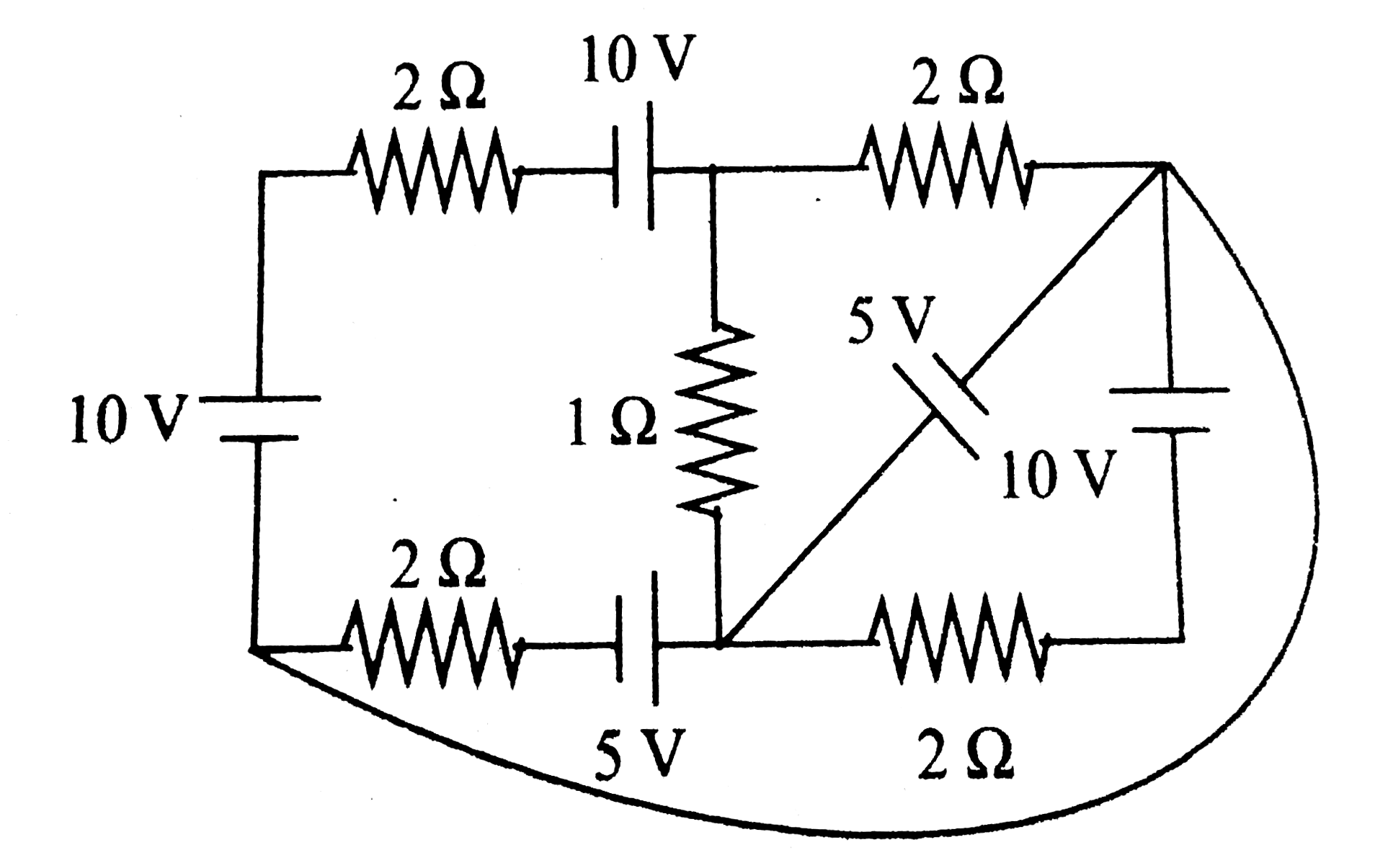
View SolutionIn the circuit diagram shown in find the current through the 1Ω resistor.
View SolutionThe circuit consists of two resistors (of resistance R1=20Ω and R2=10Ω), a capacitor (of capacitance C=10μF) and two ideal cells. In the circuit shown the capacitor is in steady state and the switch S is open
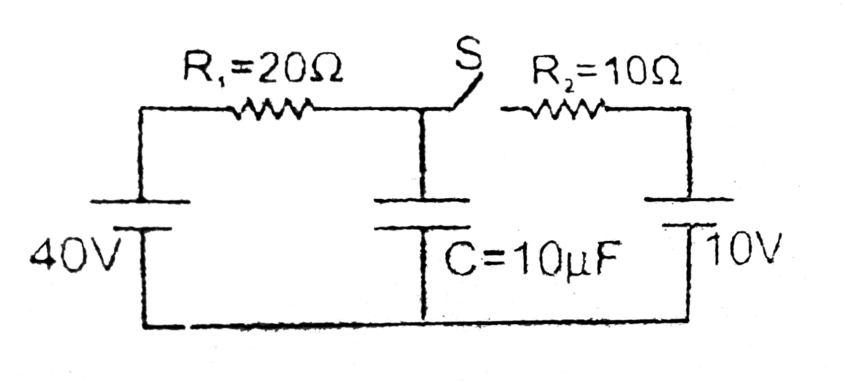
The current through the resistor R2 just after the switch S is closed is :
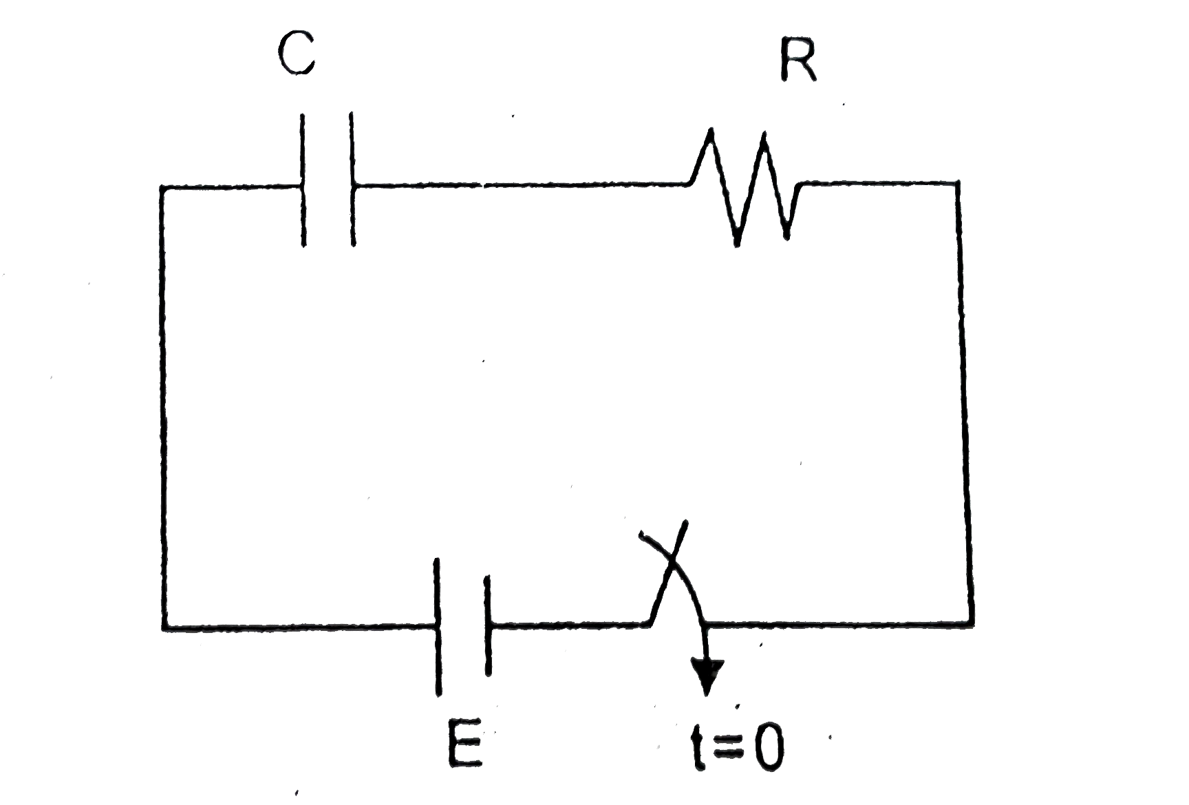
View SolutionIn the circuit shown key is closed at t=0 with capacitor initially uncharged.
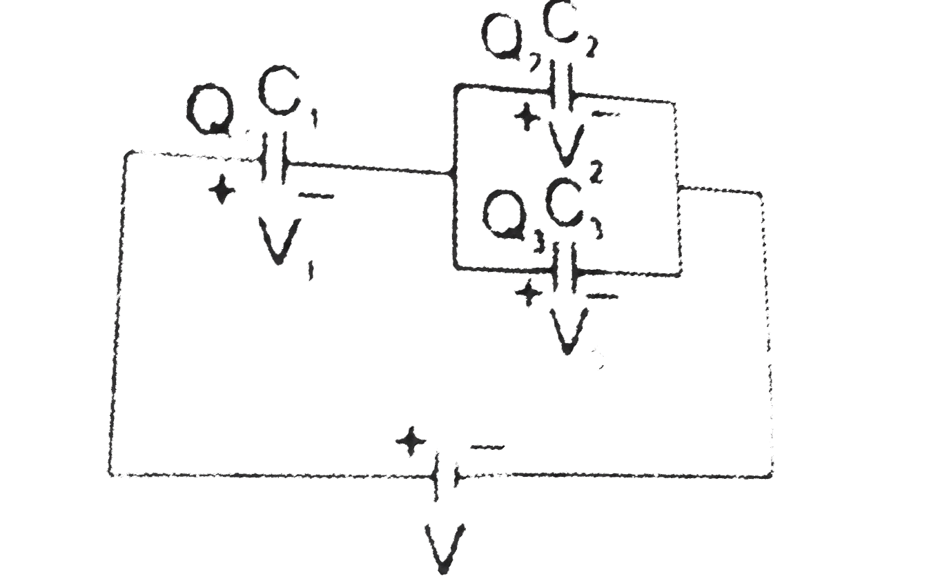
View SolutionIn the adjoining diagram all the capacitors are initially uncharged, they are connected with a battery as a shown in figure. Then
View SolutionDetermine the current through the resistor for following circuits

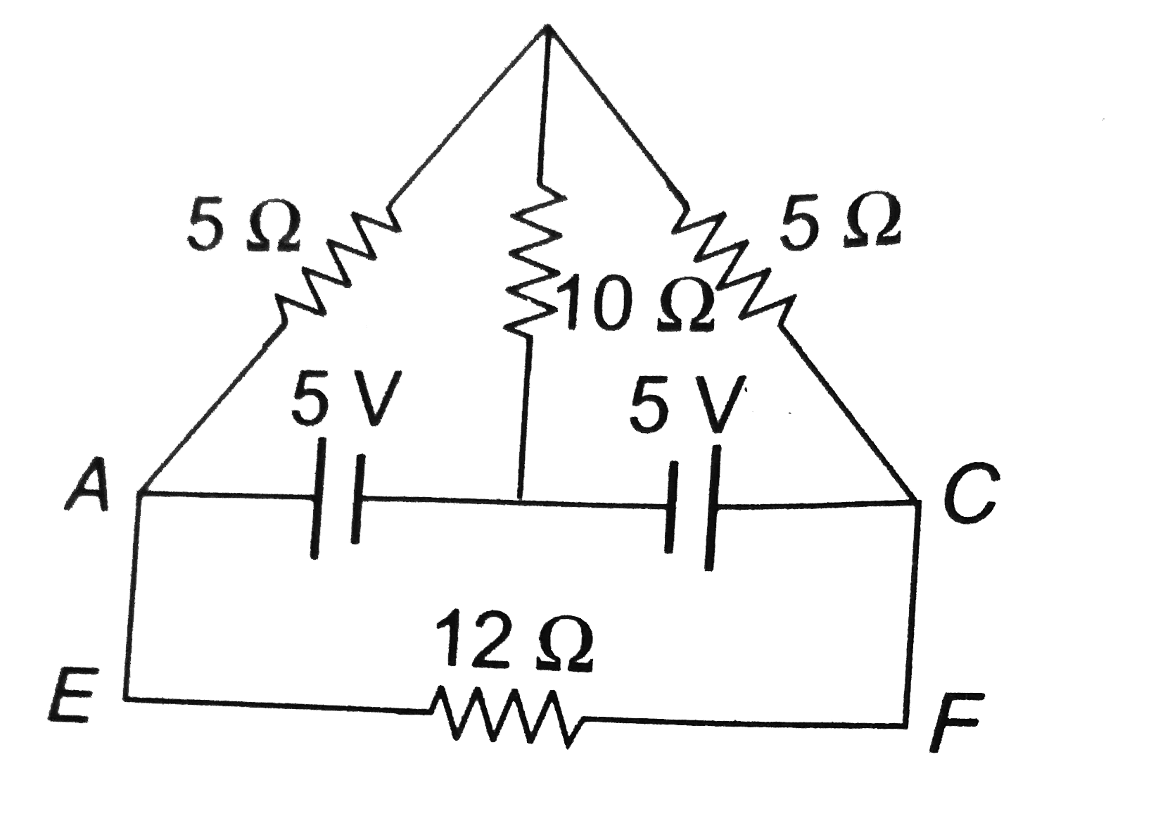
View SolutionIn the circuit of adjoining figure the current through 12Ω resister will be
View Solution
