Two capacitors, C1andC2, charged to a potential V2 and V respectively with polarities as shown, are connected in a circuit with an ideal battery of EMF V. The capacitances are C1=2C and aC_(2)=C.Att=0, the switch S is closed. A long time after S is closed,
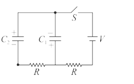
The upper plate of C1 has positive charge CV
Total charge that has flowed through battery is 3CV
Total loss in heat dissipation is 94CV2
Potential energy stored in C1 is same as potential energy stored in it at t = 0
The correct Answer is:A
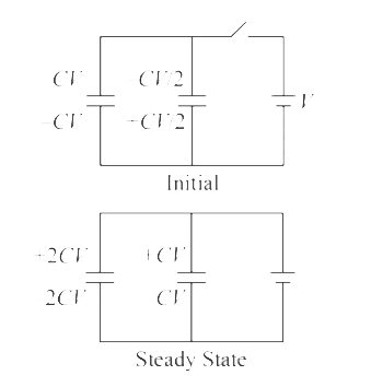
Between t=0 and the steady state,
+32CV charge flowed into upper plate of C1,
+CV charge flowed into upper plate plate of C2
So, +52CV charge flowed out of positive terminal of battery
Heat dissipation=Ui+Wbattery−Uf
=(12C(V2)2+12(2C)V2)+(52CV×V)−12CV2−12(2C)V2=74CV2.
Topper's Solved these Questions
- BOOK - VMC MODULES ENGLISHCHAPTER - CAPACITORSEXERCISE - JEE Main (Archive) LEVEL-136videos
CAPACITORS
- BOOK - VMC MODULES ENGLISHCHAPTER - CAPACITORSEXERCISE - JEE Advance ( Archive ) LEVEL 21videos
CAPACITORS
- BOOK - VMC MODULES ENGLISHCHAPTER - CAPACITORSEXERCISE - LEVEL 1 (MCQs)60videos
CAPACITORS
- BOOK - VMC MODULES ENGLISHCHAPTER - BASIC MATHEMATICS & VECTORSEXERCISE - Impeccable50videos
BASIC MATHEMATICS & VECTORS
- BOOK - VMC MODULES ENGLISHCHAPTER - CURRENT ELECTRICITYEXERCISE - IN-CHAPTER EXERCISE-F10videos
CURRENT ELECTRICITY
Similar Questions
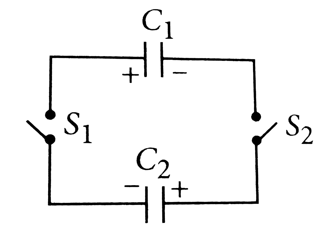
Two capacitors C1 and C2 are charged to same potential V, but with opposite polarity as shown in the figure. The switches S1 and S2 are then closed
 View Solution
Two capacitors with capacities C1 and C2 ,are charged to potentials V1 and V2 respectively.When they are connected in parallel,the ratio of their respective charges is ....?
View Solution
Knowledge Check
- Question 1 - Select One
Two capacitors C1=2μF and C2=1μF are charged to same potential V=100V, but with opposite polarity as shown in the figure.
The switches S1 and S2 are closed. The ratio of final energy to the initial energy of the system is
 A1B12C19D14
Two capacitors C1=4μFandC2=2μF are charged to same potential V = 500 Volt, but with opposite polarity as shown in the figure. The switches S1andS2 are closed.
 View Solution
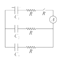
A capacitor C1 is charged to a potential V and connected as shown with capacitors C2andC3 both of which are initially uncharged. Capacitance of all capacitors is C. The ammeter is ideal. At t=01 switch S is closed. Pick the correct choice(s):
 View Solution
Three capacitors of capacitances 5μF,2μF and 2μF are charged to 20 V, 30 V and 10 V respectively and then connected in the circuit with polarities as shown. The magnitude of charge flown through the battery after closing the switch S isView SolutionTwo capacitors C1 and C2 of capacitances C2 and C4 are connected to a V volt battery, as shown in figure. The ratio of energy slored in capacitors C1 and C2 is
 View Solution
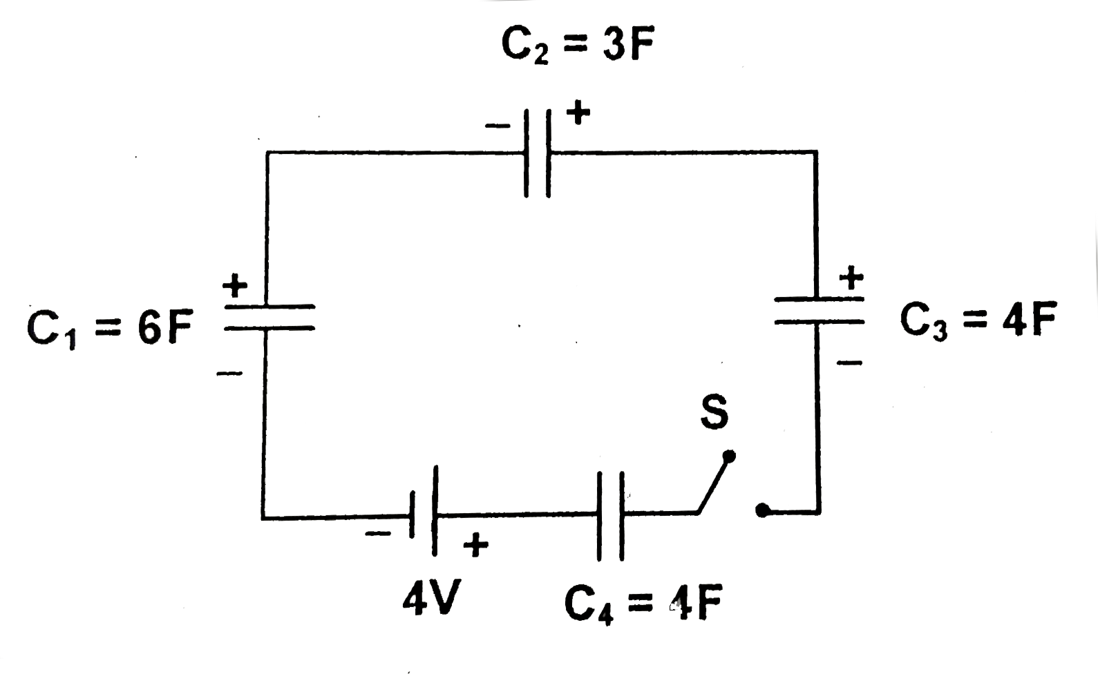
Three capacitor C1=6F,C2=3F and C3=4F are separately charged with battery such that charge on each capacitor are 36C,24C and 40C respectively and then disconnected with the battery. After that they are connected in a circuit along with an uncharged capacitor C4=4F and a battery of emf =4 volts as shown figure. Now the switch S is closed. Choose is correct option (s).
 View Solution
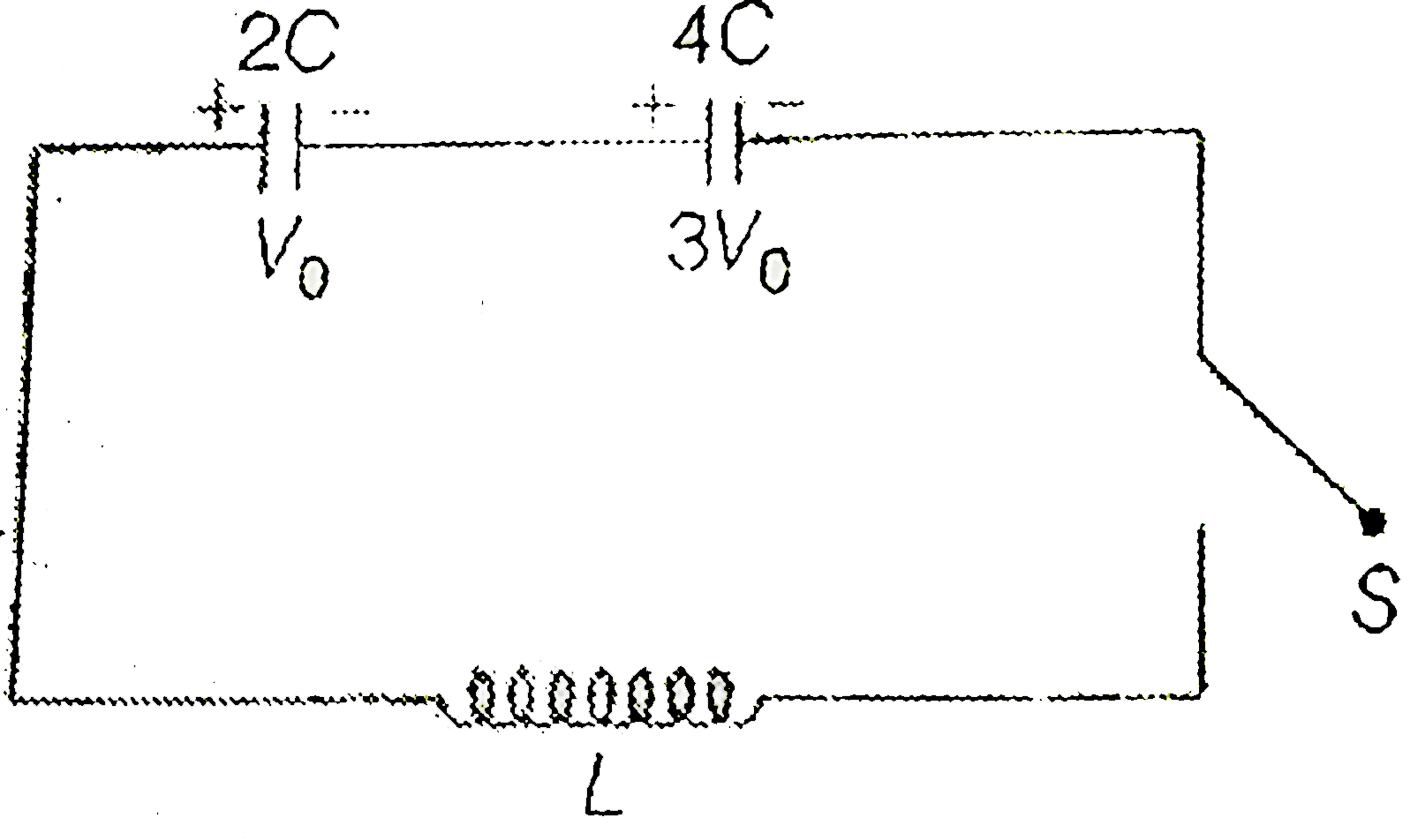
Two capacitors 2C and 4C initially charged to potential difference of V0and3V0 with the potential as show are connected to an inductor of inductance L. Initial curren tin the inductor is zer. Now the swtich 'S' is closed. The maxmimum current in the circuit is
 View Solution
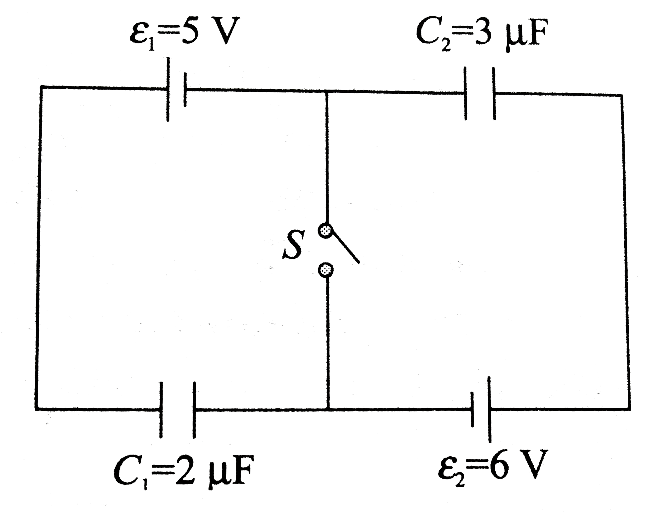
Two capacitors C1andC2 are connected with two batteries of emf ε1 and ε2. The circuit components are connected with a switch S as shown in. Initially the switch is open and the capacitors are charged. Find the heat produced when switch S is closed.
 .View Solution

