In the circuit shown and are cells of emf and respectively and their internal resistance are and respectively.
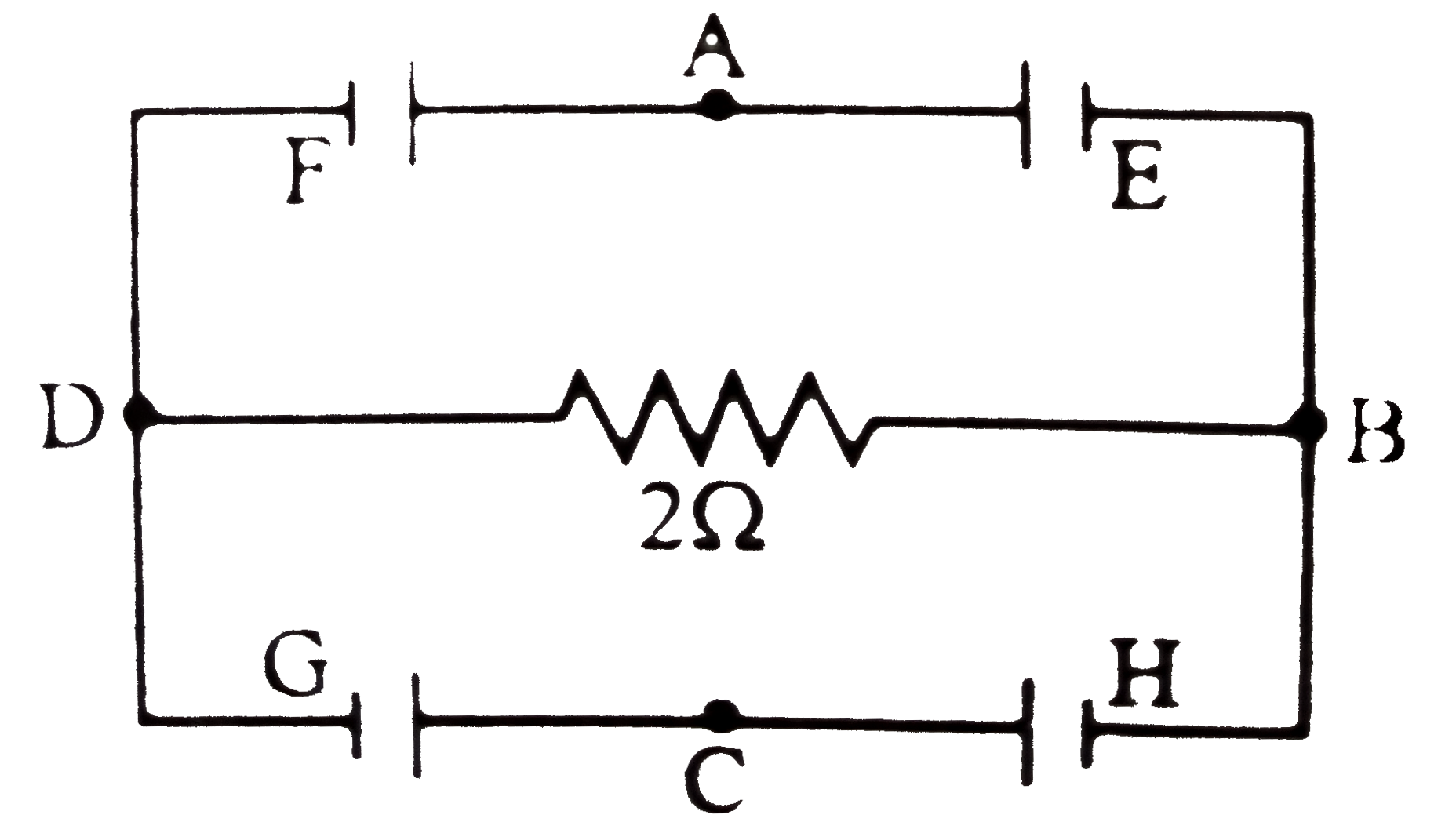
=
=
=
ACD
Topper's Solved these Questions
- DC CIRCUITBOOK - VMC MODULES ENGLISHCHAPTER - DC CIRCUITEXERCISE - LEVEL-1 JEE MAIN ARCHIVE
93 Videos
- DC CIRCUITBOOK - VMC MODULES ENGLISHCHAPTER - DC CIRCUITEXERCISE - JEE ADVANCED ARCHIVE
68 Videos
- DC CIRCUITBOOK - VMC MODULES ENGLISHCHAPTER - DC CIRCUITEXERCISE - LEVEL-2 DAILY TUTORIAL SHEET-4
10 Videos
- CURRENT ELECTRICITYBOOK - VMC MODULES ENGLISHCHAPTER - CURRENT ELECTRICITYEXERCISE - IN-CHAPTER EXERCISE-F
10 Videos
- DYNAMICS OF A PARTICLEBOOK - VMC MODULES ENGLISHCHAPTER - DYNAMICS OF A PARTICLEEXERCISE - JEE Advance (Archive) Level - II (SINGLE OPTION CORRECT TYPE )
31 Videos
Similar Questions
In the circuit shown in figure
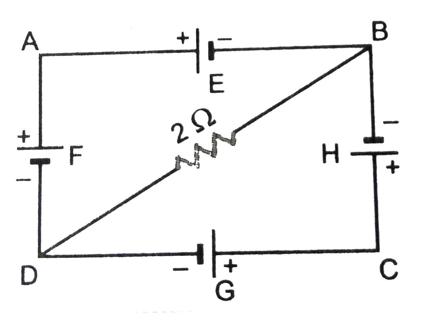
16, E, F, G and H are cells of emf 2V,1V,3Vand1V and their internal resistance are 2Ω,1Ω,3Ω and 1Ω respectively. Calculate (i) the potential differnce between B and D and (ii) the potential difference across the terminals of each of the cells G and H.
View SolutionIn the circuit shown in E, F, G, and H are cells of emf 2,1,3 and 1 V, respectively. The resistances 2Ω,1Ω,3Ωand1Ω are their respectivle internal resistances.
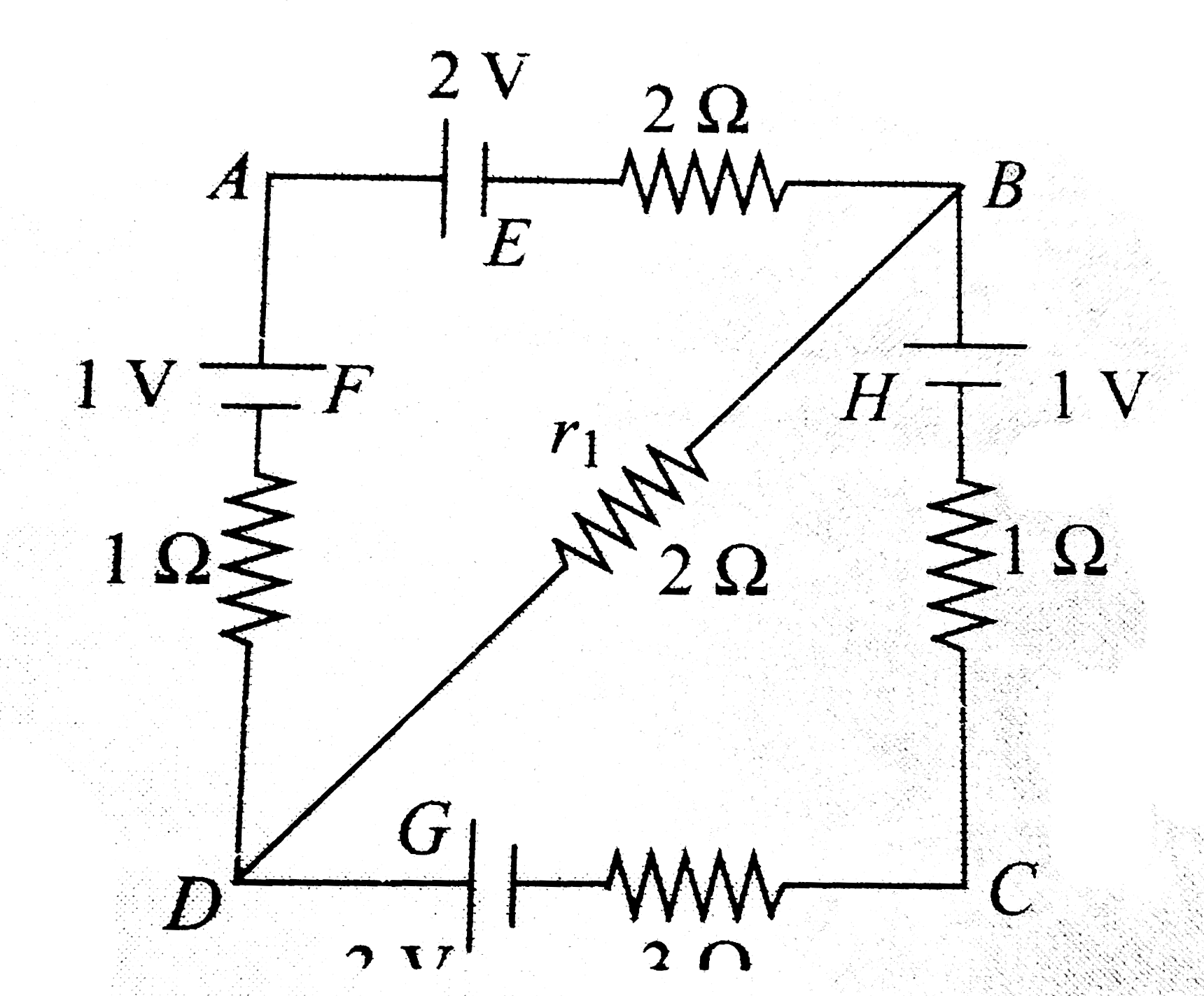
i. Find the potential difference between B and D.
(ii) Calculate the potential differences across the terminals of each of the cells G and H.
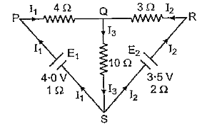
View SolutionIn the circuit shown in figure below, E1 and E2 are batteries having emfs 4.0 V and 3.5 V respectively and internal resistance 1Ω and 2Ω respectively. Using Kirchhoff.s laws, calculate currents : I1,I2 and I3.
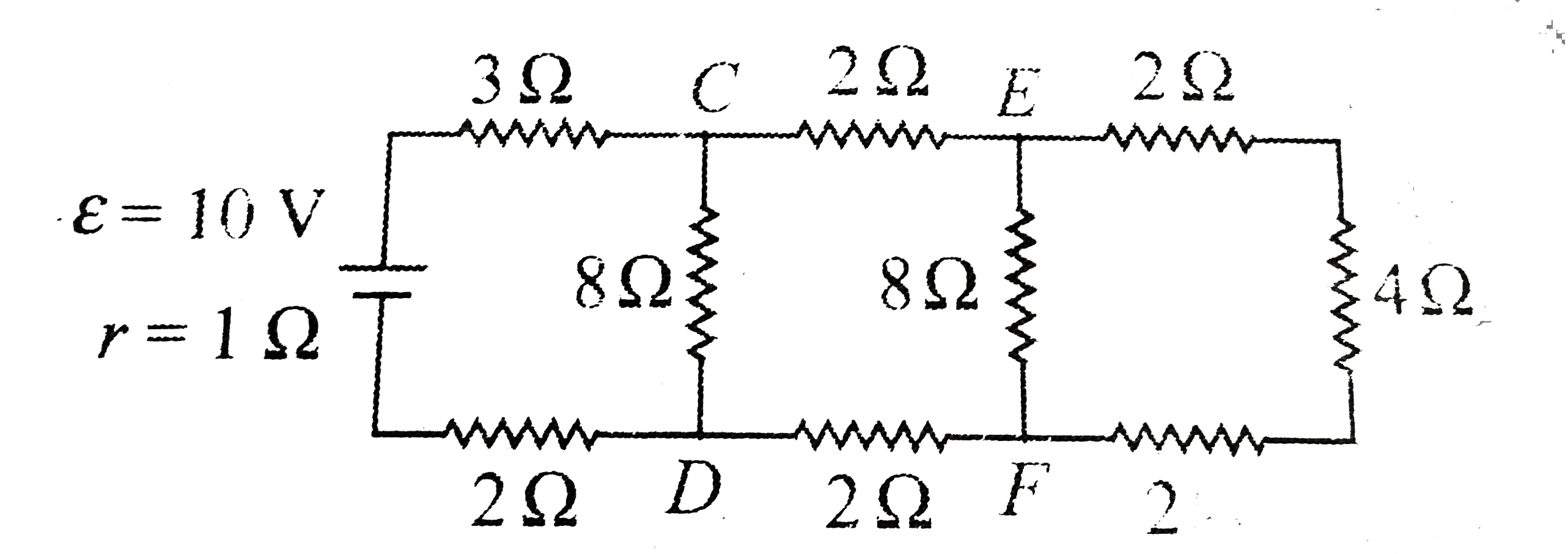
View SolutionIn the circuit shown in fig. the cell has emf 10V and internal resistance 1Ω
View SolutionA potentiometer circuit is shown in Figure 3 below. AB is a uniform metallic wire having length of 2m and resistance of 8Ω. The batteries E1andE2 have emfs of 4V and 1.5V and their internal resistances are 1Ωand2Ω respectively.
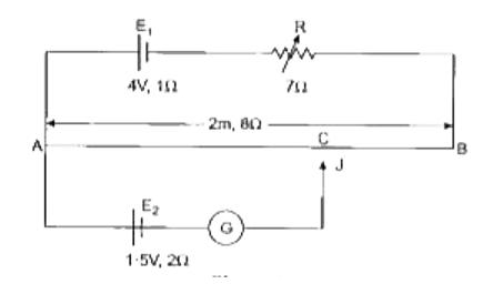
Now the jockey J is made to touch the wire AB at a point C such that the galvanometer (G) shows no deflection. Calculate the length AC.
View SolutionA potentiometer circuit is shown in Figure 3. AB is a uniform metallic wire having length of 2 m and resistance of 8Ω. The batteries E1andE2 have emfs of 4V and 1.5 V and their internal resistance are 1Ω and 2Ω respectively.
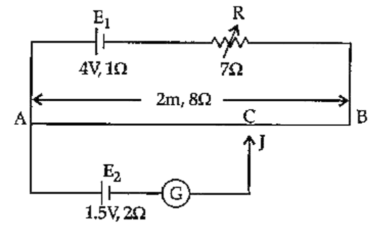
If the jockey J is made to touch the wire AB at a point C such that the galvanometer (G) shows no defection. Calculate the length AC.
View SolutionA potentiometer circuit is shown in Figure 3 below. AB is a uniform metallic wire having length of 2m and resistance of 8Ω. The batteries E1andE2 have emfs of 4V and 1.5V and their internal resistances are 1Ωand2Ω respectively.
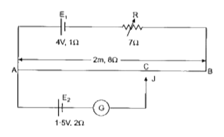
When the jockey J does not touch the wire AB, calculate:
the potential gradient across the wire AB
View SolutionA potentiometer circuit is shown in Figure 3. AB is a uniform metallic wire having length of 2 m and resistance of 8Ω. The batteries E1andE2 have emfs of 4V and 1.5 V and their internal resistance are 1Ω and 2Ω respectively.
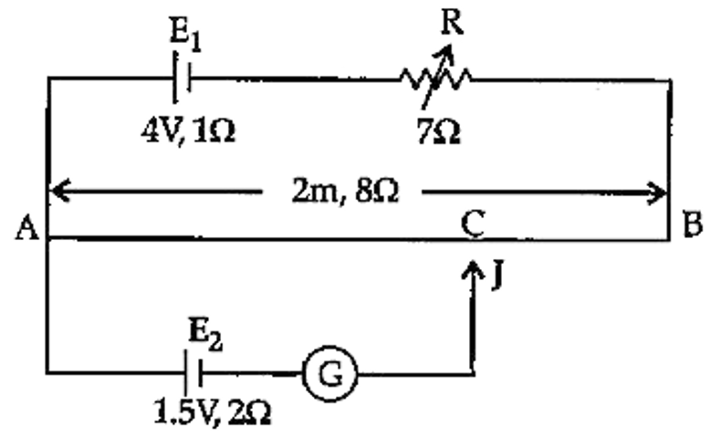
When the jockey J does not touch the wire AB, calculate :
(a) the current flowing through the potentiometer wire AB.
(b) the potential gradient across the wire AB.
View SolutionA potentiometer circuit is shown in Figure 3 below. AB is a uniform metallic wire having length of 2m and resistance of 8Ω. The batteries E1andE2 have emfs of 4V and 1.5V and their internal resistances are 1Ωand2Ω respectively.
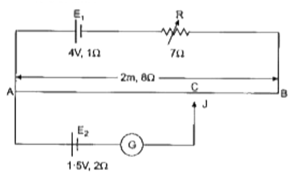
When the jockey J does not touch the wire AB, calculate:
the current flowing through the potentiometer wire AB.
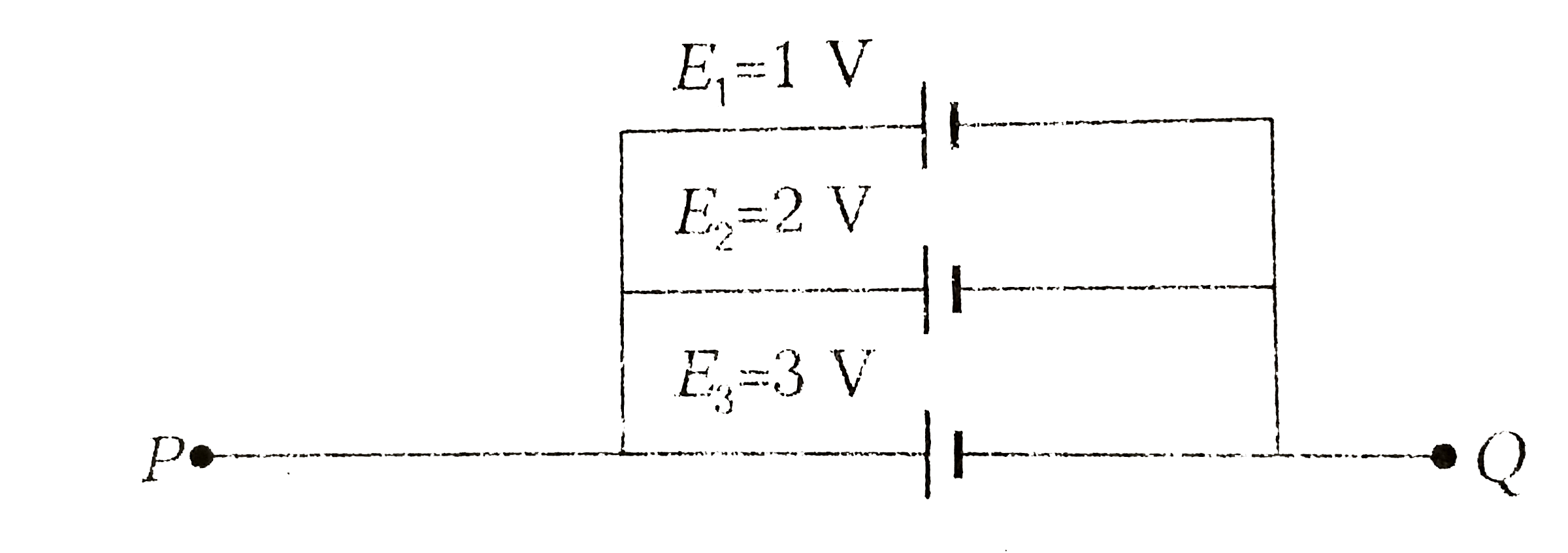
View SolutionA circuit consists of three bateries of emf E1=1V,E2=2V and E3=3V and internal resistance 1Ω,2Ω and 1Ω respectively which are connected in parallel as shown in figure. The potential difference between points P and Q is
View Solution
