In the circuit shown in figure 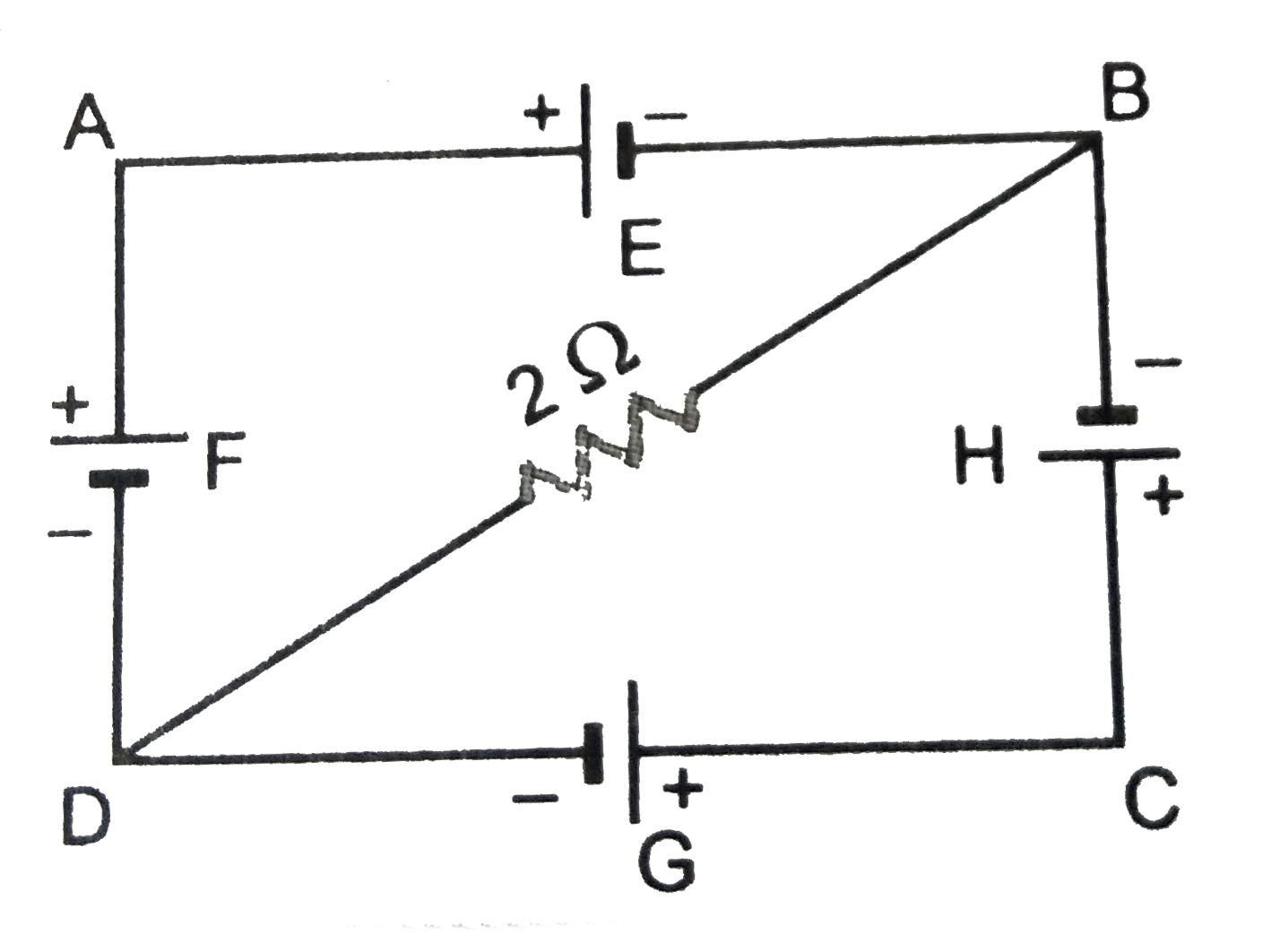
16, E, F, G and H are cells of emf 2V,1V,3Vand1V and their internal resistance are 2Ω,1Ω,3Ω and 1Ω respectively. Calculate (i) the potential differnce between B and D and (ii) the potential difference across the terminals of each of the cells G and H.
The correct Answer is:(i) 11
(ii) 19
Step by step video & image solution for In the circuit shown in figure 16, E, F, G and H are cells of emf 2 V, 1 V, 3 V and 1 V and their internal resistance are 2 Omega, 1 Omega, 3 Omega and 1 Omega respectively. Calculate (i) the potential differnce between B and D and (ii) the potential difference across the terminals of each of the cells G and H. by Physics experts to help you in doubts & scoring excellent marks in Class 12 exams.
Updated on:21/07/2023Topper's Solved these Questions
- CURRENT ELECTRICITYBOOK - RESONANCE ENGLISHCHAPTER - CURRENT ELECTRICITYEXERCISE - Exercise-2 (Part-3)
22 Videos
- CURRENT ELECTRICITYBOOK - RESONANCE ENGLISHCHAPTER - CURRENT ELECTRICITYEXERCISE - Exercise-2 (Part-4)
12 Videos
- CURRENT ELECTRICITYBOOK - RESONANCE ENGLISHCHAPTER - CURRENT ELECTRICITYEXERCISE - Exercise-2 (Part-1)
24 Videos
- COMMUNICATION SYSTEMSBOOK - RESONANCE ENGLISHCHAPTER - COMMUNICATION SYSTEMSEXERCISE - Exercise 3
13 Videos
- DAILY PRACTICE PROBLEMBOOK - RESONANCE ENGLISHCHAPTER - DAILY PRACTICE PROBLEMEXERCISE - DPP.No.71
1 Videos
Similar Questions
In the circuit shown E,F,G and H are cells of emf 2V,1V,3V and 1V respectively and their internal resistance are 2Ω,1Ω,3Ω and 1Ω respectively.
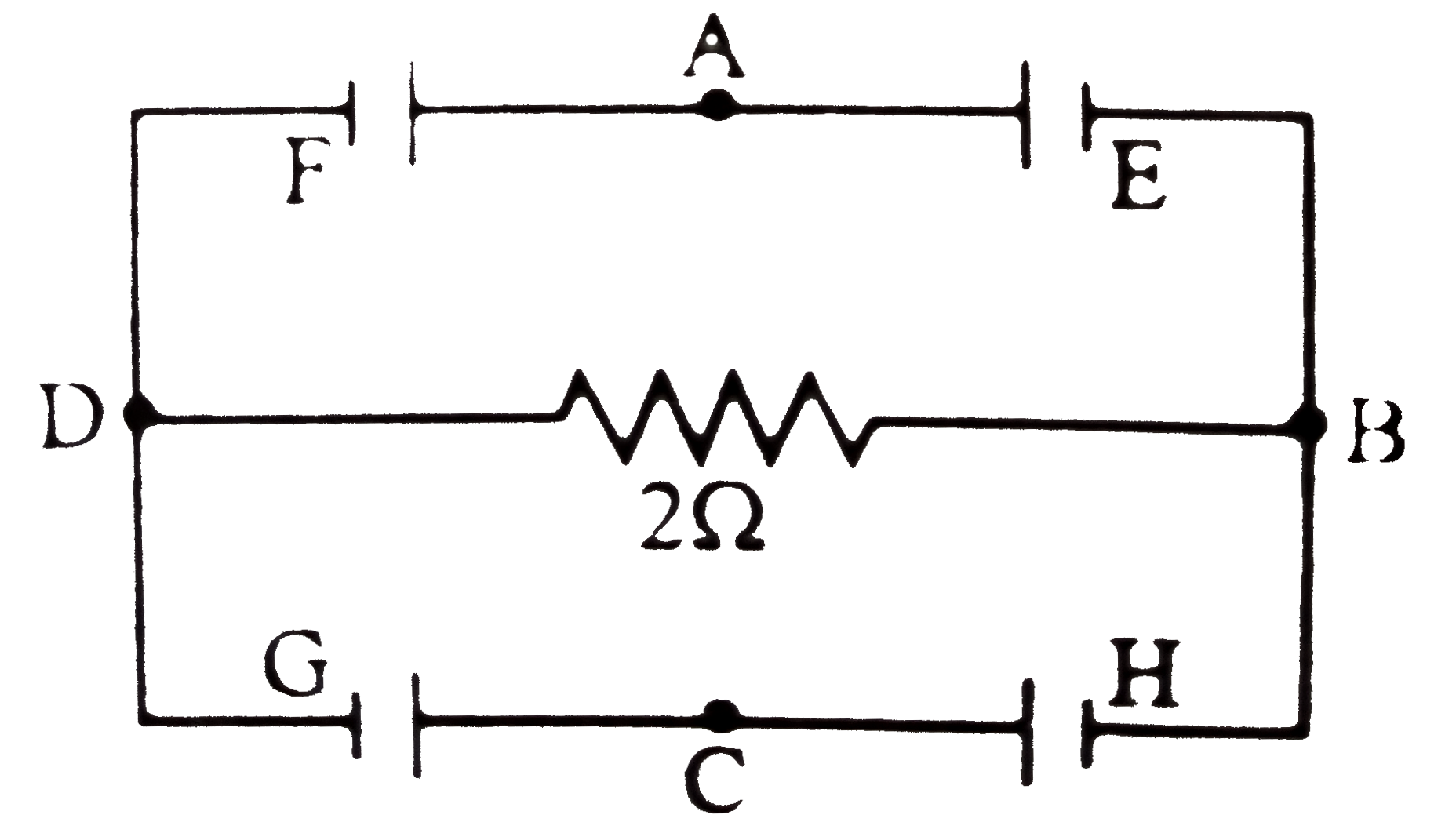
View SolutionIn the circuit shown E,F,G and H are cells of emf 2V,1V,3V and 1V respectively and their internal resistance are 2Ω,1Ω,3Ω and 1Ω respectively.

View SolutionIn the circuit shown in E, F, G, and H are cells of emf 2,1,3 and 1 V, respectively. The resistances 2Ω,1Ω,3Ωand1Ω are their respectivle internal resistances.

i. Find the potential difference between B and D.
(ii) Calculate the potential differences across the terminals of each of the cells G and H.
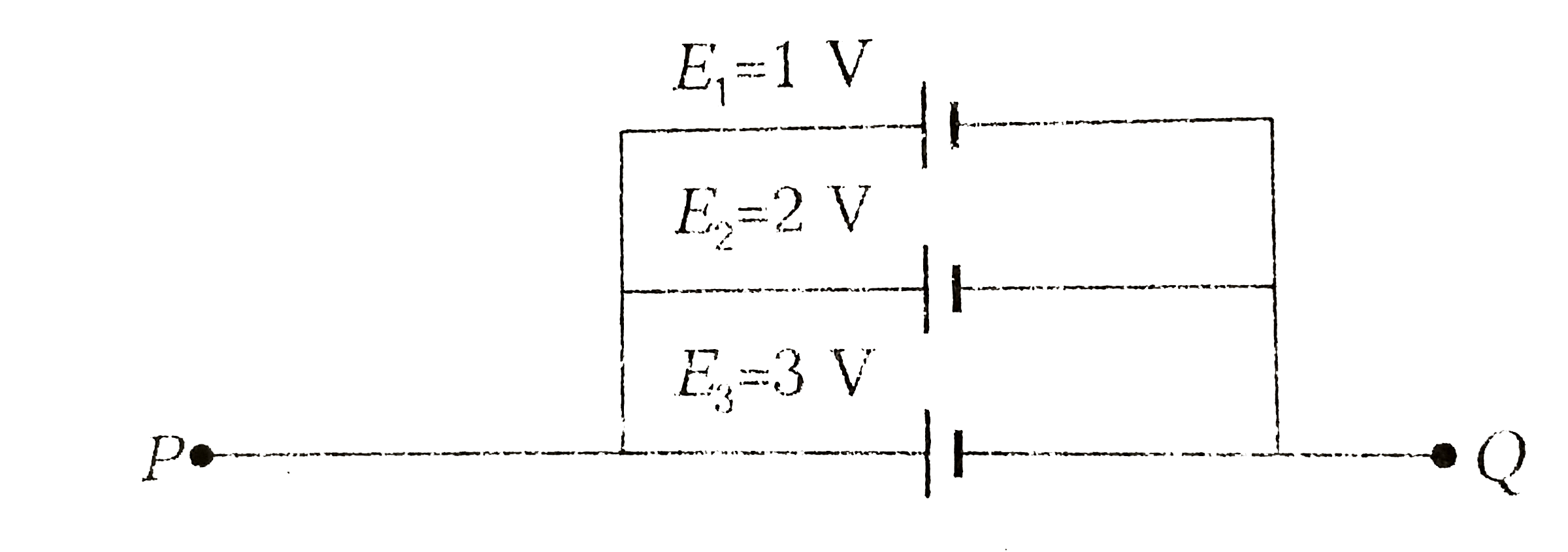
View SolutionA circuit consists of three bateries of emf E1=1V,E2=2V and E3=3V and internal resistance 1Ω,2Ω and 1Ω respectively which are connected in parallel as shown in figure. The potential difference between points P and Q is
View SolutionIn the ciruit the cells E1andE2 have emfs of 4V and 8V and internal resistance 0.5Ωand1.0Ω, respectively. Calculate the current through 6Ω resistance.

View SolutionTwo non-ideal batteries have e.m.f 2V and 8V respective ly and internal resistance 1 Omega and 2 Omega respectively as shown in the figure. If the potential difference between a and b is zero then the resistance R has a value
_PHY_E01_014_Q01.png)
View SolutionA cell of e.m.f. 1.8 V and internal resistance 2 Ω is connected in series with an ammeter of resistance 0.7 Ω and a resistor of 4.5 Ω as shown in Fig. What is the potential difference across the terminals of the cell ?

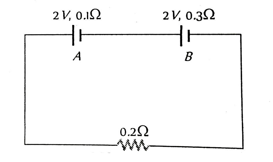
View SolutionThe internal resistances of two cells shown are 0.1Ω and 0.3Ω. If R=0.2Ω, its potential difference across the cell
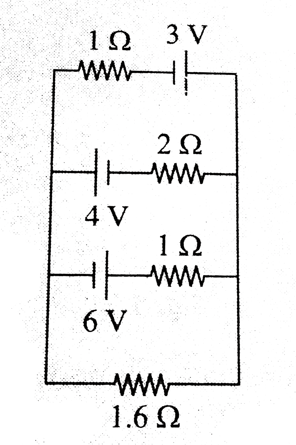
View SolutionThree cells of emf 3V, 4V, and 6V are connected in parallel, If their internal resistances are 1Ω, 2 Omegaand1Ω find the εeff,reff, and the current in the external load R = 1.6 Ω .
View SolutionA cell of emf 2 V and internal resistance 1.2Ω is connected with an ammeter of resistance 0.8Ω and two resistors of 4.5Ωand9Ω as shown in the diagram below:
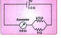
What is the potential difference across the terminals of the cell ?
View Solution
