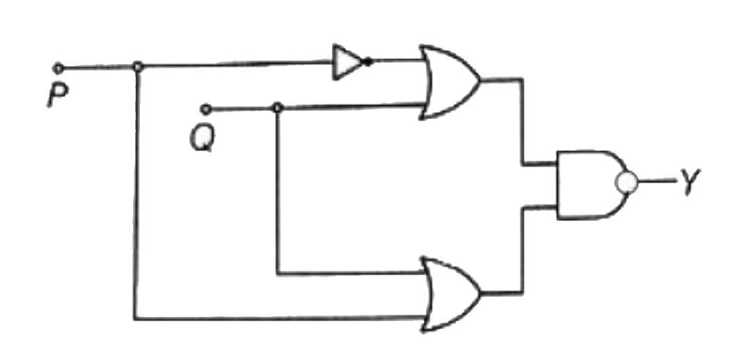
The circuit diagram (see fig.) shows a 'logic combination' with the states outputs X,Y and Z given for input P,Q,R and S all at state 1 (i.e., high). When inputs P and R change to state 0 i.e., low) with inputs Q and S still at 1, the condition of output X,Y and Z chages to
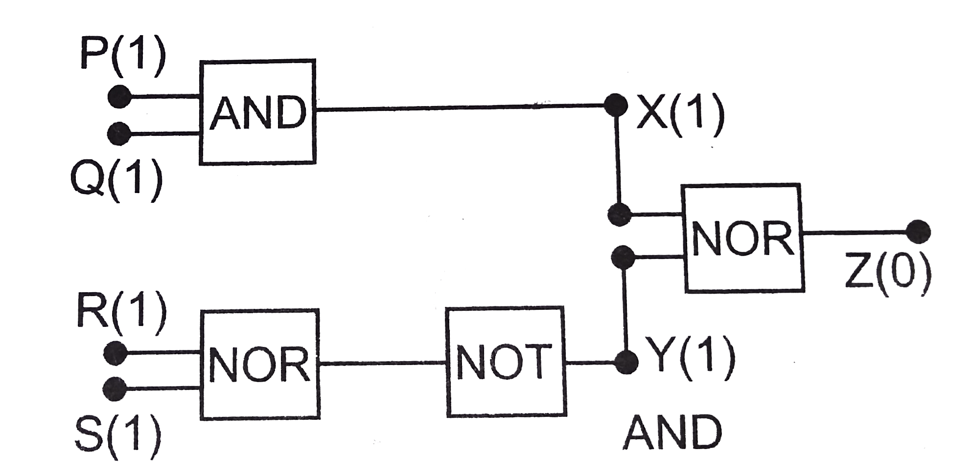
X=0,Y=0,Z=0
X=1,Y=1,Z=1
X=0,Y=1,Z=0
X=1,Y=0,Z=0
The correct Answer is:C
Step by step video & image solution for The circuit diagram (see fig.) shows a 'logic combination' with the states outputs X,Y and Z given for input P,Q,R and S all at state 1 (i.e., high). When inputs P and R change to state 0 i.e., low) with inputs Q and S still at 1, the condition of output X,Y and Z chages to by Physics experts to help you in doubts & scoring excellent marks in Class 12 exams.
Updated on:21/07/2023Similar Questions
Knowledge Check
Three different functions are defined in the table below .
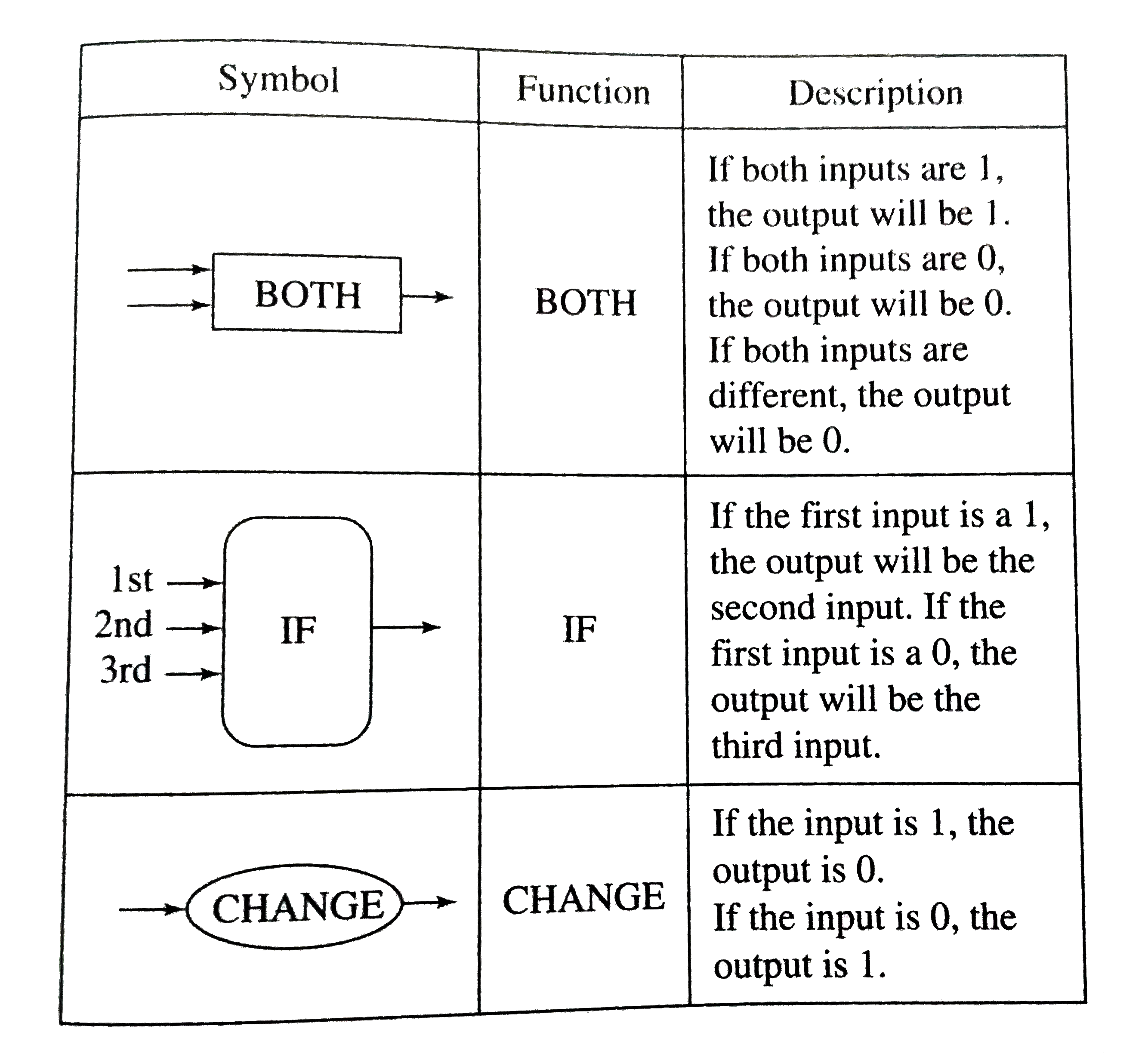
The diagram below uses functions . The only values for p,q,r,s and t are 1 and 0 . Which of the following inputs (p,q,r,s,t) will produce the output 0 ?
 A(0,1,1,0,1)B(0,1,1,1,1)C(0,0,1,0,1)D(1,0,1,0,0)
(i) Identify the logic gates marked P and Q in the given logic circuit Fig.

(ii) Write down the output at X for the inputs A=0,B=0 and A=1,B=1.
View Solution(i) Identify the logic gates marked P and Q in the given logic circuit.
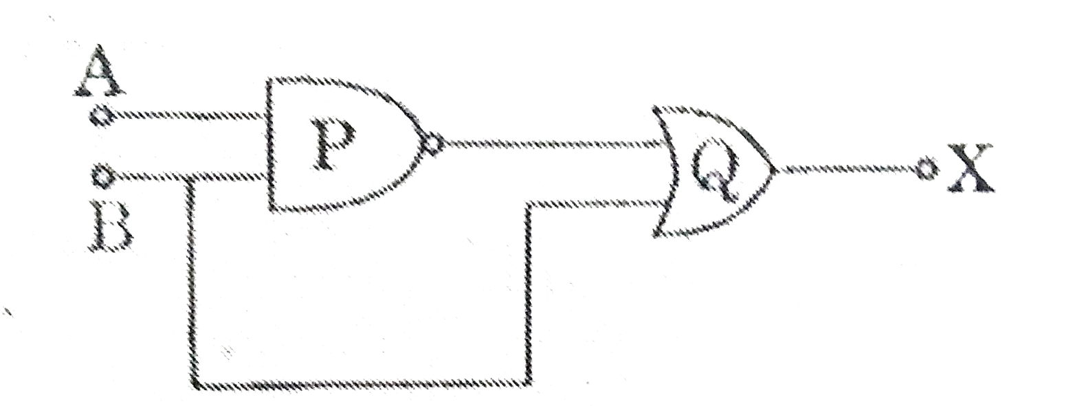
(ii) Write down the output at X for the inputs A = 0 , B = 0 and A = 1 , B = 1.
View SolutionThe lines x=y=z meets the plane x+y+z=1 at the point P and the sphere x2+y2+z2=1 at the point R and S, then
View SolutionFigure below shows the circuit of an electronic device :
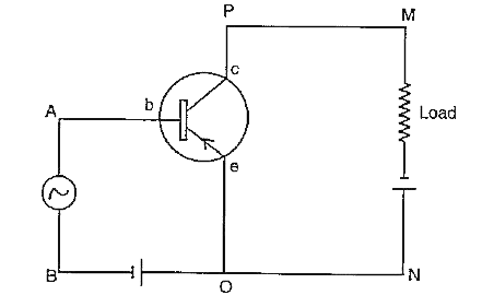
(i) Which electronic device : a rectifier, an amplifier or an oscillator does the above circuit represent?
(ii) State where the input voltage is applied and 1 where the output voltage is available.
(iii) Compare the output voltage of this circuit with its input voltage.
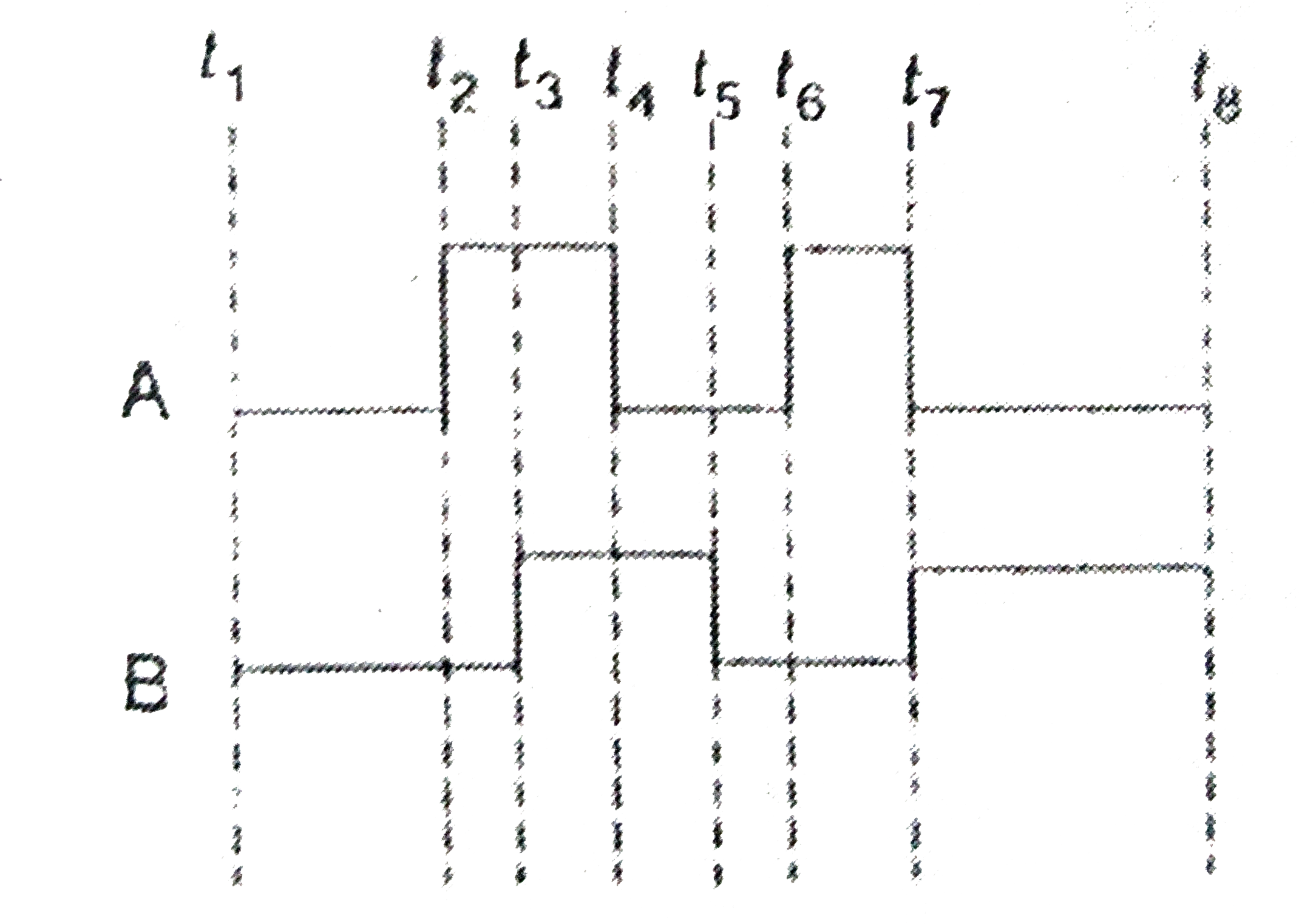
View Solution(a) Draw the circuit diagram of a full wave rectifier using p-n junction diole. Explain its working and show the output, input waveforms.
(b) Show the output waveforms (Y) for the following inputs A and B of (i) OR gate (ii) NAND gate :
View SolutionA plane meets the coordinate axes in A,B,C such that the centroid of triangle ABC is the point (p,q,r). Show that the equation of the plane is xp+yq+zr=3.
View SolutionThe amplifiers X,Y and Z are connected in series. If the voltage gains of X,Y and Z are 10,20 and 30, respectively and the input signal is 1mV peak value, then what is the output signal voltage (peak value)
(i) if dc supply voltage is 10V ?
(ii) if dc supply voltage is 5V?
View Solution

