Shown below is a graph of current versus applied voltage for a diode . Approximately , what is the resistance of the diode for an applied voltage of – 1 V ?
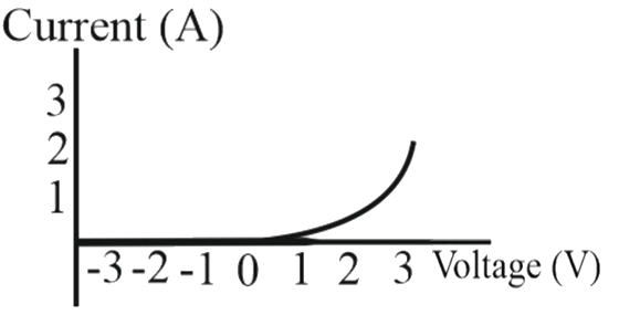
2Ω
∞
Zero
1Ω
The correct Answer is:B
Step by step video & image solution for Shown below is a graph of current versus applied voltage for a diode . Approximately , what is the resistance of the diode for an applied voltage of – 1 V ? by Physics experts to help you in doubts & scoring excellent marks in Class 12 exams.
Updated on:21/07/2023Similar Questions
Reverse bias applied to a junction diode
View SolutionPlot a graph showing variation of current versus voltage for the material Ga.
View SolutionThe cut-in voltage of a germanium diode is approximately equal to
View SolutionIf the forward voltage in a diode is increased, the width of the depletion region-
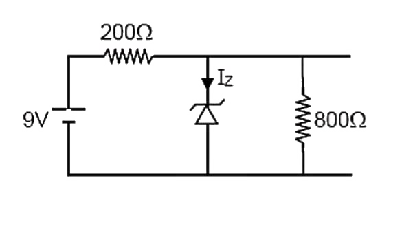
View SolutionIn the figure, the reverse breakdown voltage of a Zener diode is 5.6V, then the current IZ through the diode is
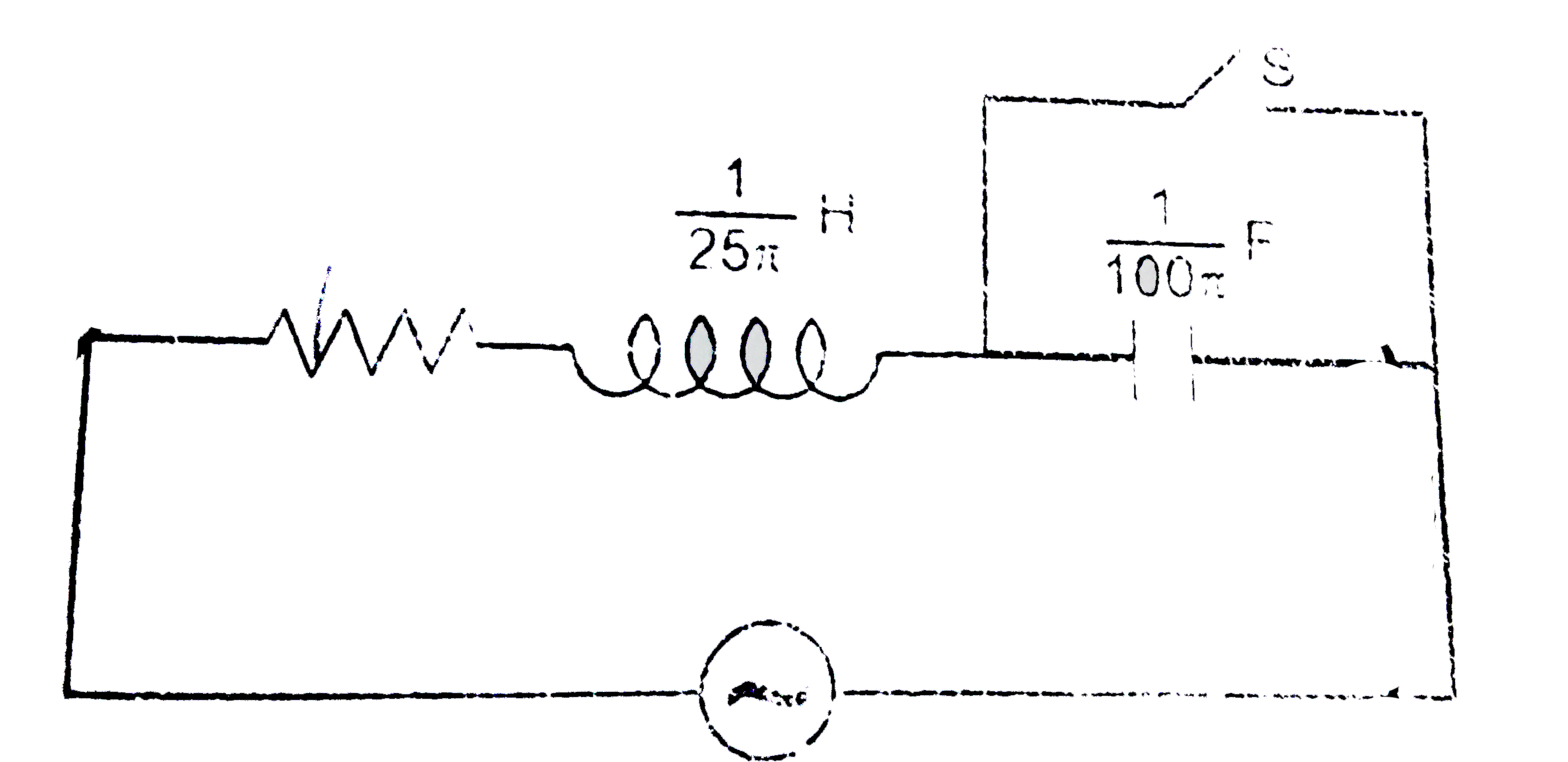
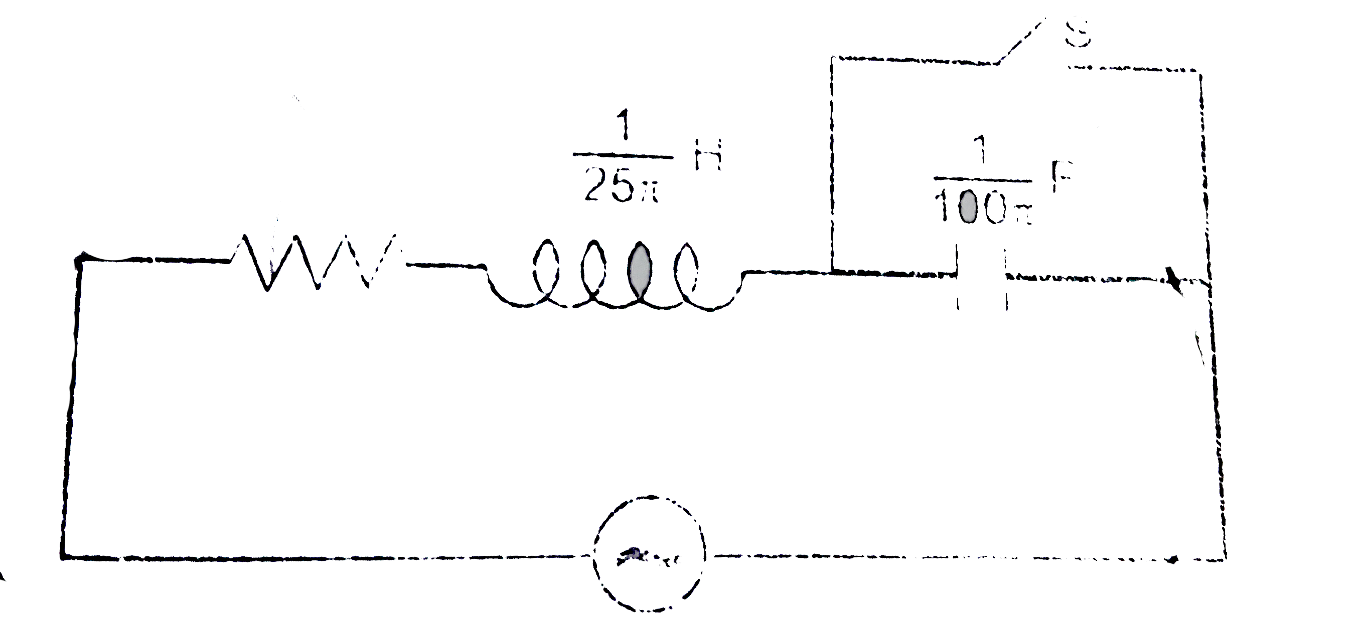
View SolutionIn the LCR circuit shown in figure unknown resistance and alternating voltage source are connected.When swith S is closed then there is a phase difference of π4 between current and applied voltage and voltage across resister is 100√2V.When switch is open current and applied voltage are in same phase.Neglecting resistance of connecting wire answer the following questions :
Peak voltage of applied voltage sources is:
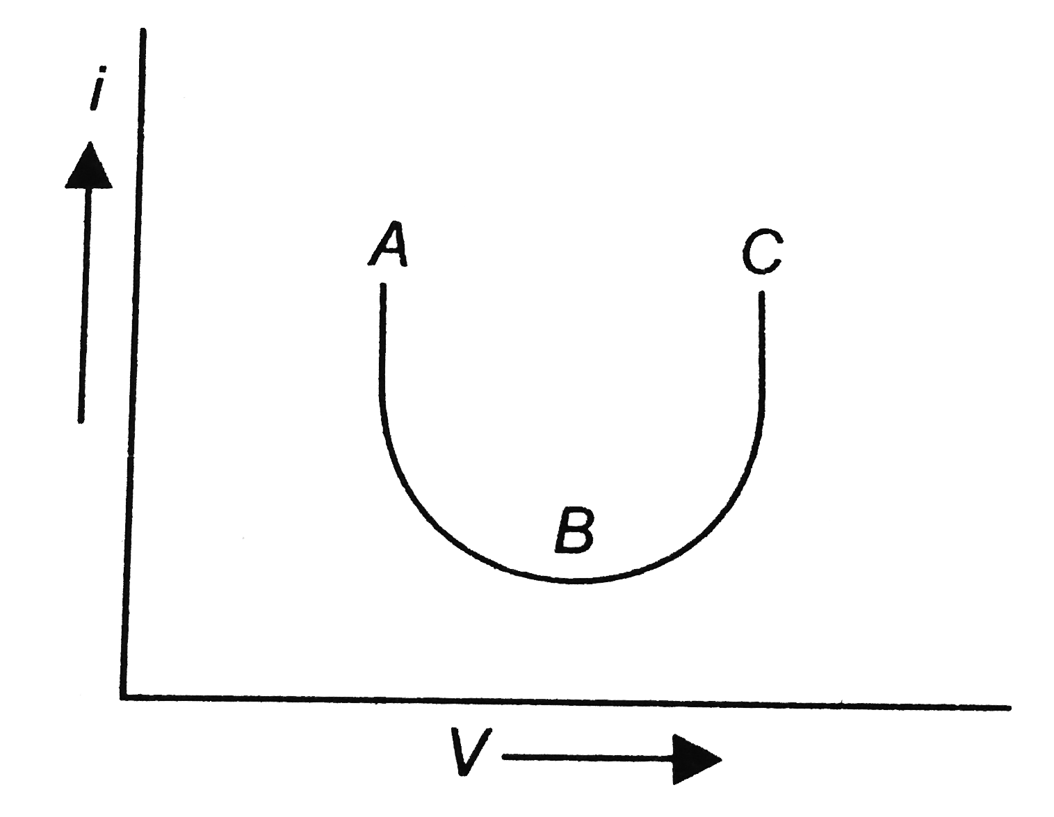
View SolutionThe current-voltage graph of a device is shown in figure. The resistance is negative in region.
View SolutionIn the LCR circuit shown in figure unknown resistance and alternating voltage source are connected.When swith S is closed then there is a phase difference of π4 between current and applied voltage and voltage across resister is 100√2V.When switch is open current and applied voltage are in same phase.Neglecting resistance of connecting wire answer the following questions :
Resonance frequency of circuit is:
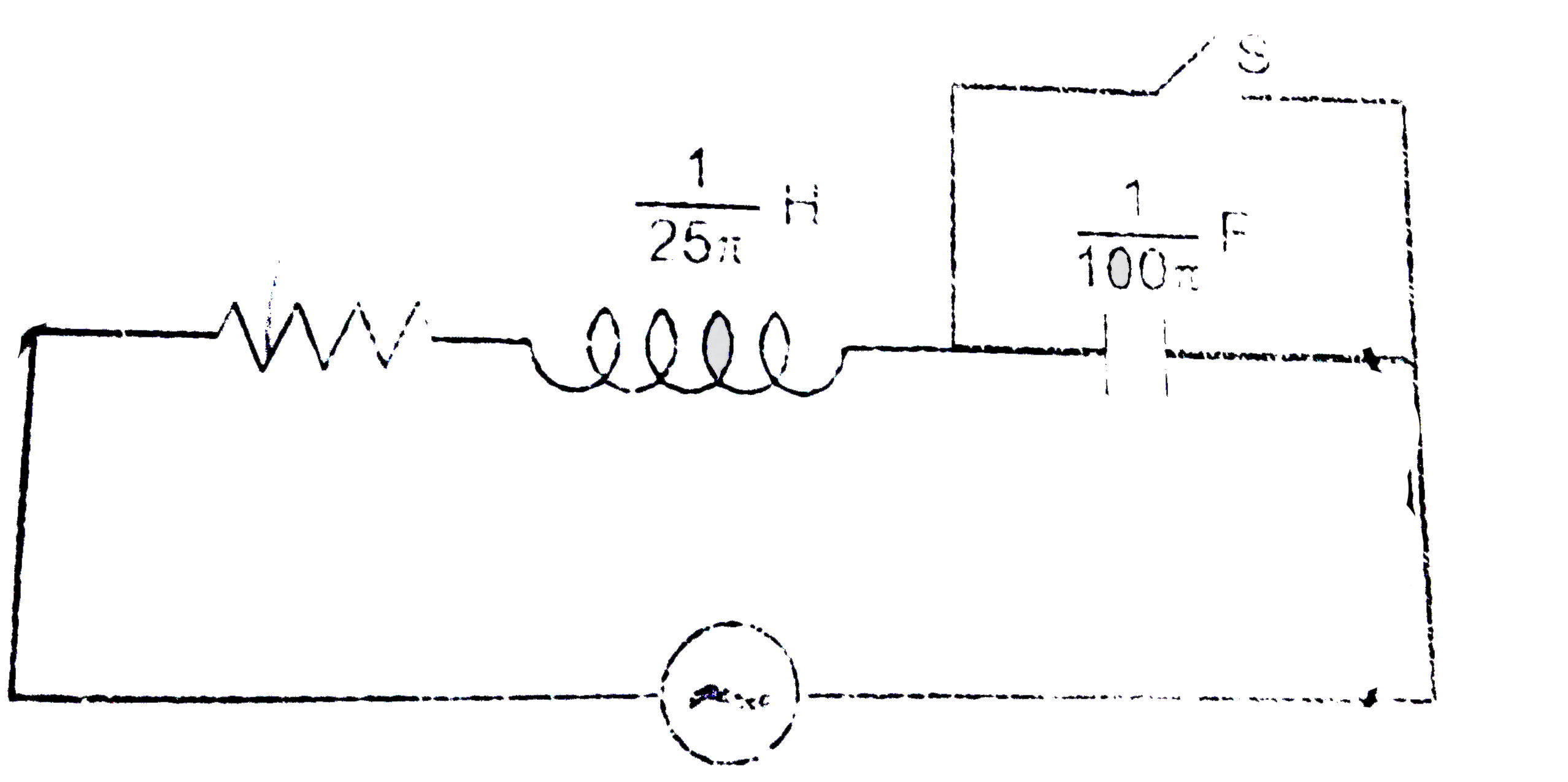
View SolutionIn the LCR circuit shown in figure unknown resistance and alternating voltage source are connected.When swith S is closed then there is a phase difference of π4 between current and applied voltage and voltage across resister is 100√2V.When switch is open current and applied voltage are in same phase.Neglecting resistance of connecting wire answer the following questions :
Average power consumption in the circuit when S is open:
View SolutionThe forward characteristic curve of a junction diode is shown in figure below:
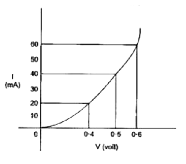
Calculate the resistance of the diode at:
y= 0.5V
View Solution