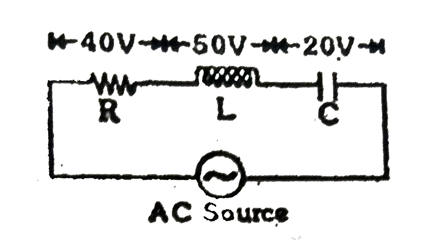
In a series LCR circuit, the voltages across an inductor, a capacitor and a resistor are 30 V, 30 V, 60 V respectively. What is the phase difference between the applied voltage and the current in the circuit ?
To find the phase difference between the applied voltage and the current in a series LCR circuit, we can follow these steps:
Step 1: Identify the given values
We have the following voltages in the circuit:
- Voltage across the inductor, VL=30V
- Voltage across the capacitor, VC=30V
- Voltage across the resistor, VR=60V
Step 2: Use the formula for the phase angle
In a series LCR circuit, the phase angle ϕ between the applied voltage and the current can be calculated using the formula:
tanϕ=XL−XCR
where XL is the inductive reactance, XC is the capacitive reactance, and R is the resistance.
Step 3: Relate voltages to reactances and resistance
We know that:
- VL=I⋅XL
- VC=I⋅XC
- VR=I⋅R
From these relationships, we can express XL and XC in terms of the voltages and current:
XL=VLI,XC=VCI,R=VRI
Step 4: Substitute the values into the formula
Substituting VL, VC, and VR into the equation for tanϕ:
tanϕ=VLI−VCIVRI=VL−VCVR
Now, substituting the given voltages:
tanϕ=30V−30V60V=060=0
Step 5: Determine the phase angle
Since tanϕ=0, we have:
ϕ=0∘
Conclusion
The phase difference between the applied voltage and the current in the circuit is 0∘.
---
We have the following voltages in the circuit:
- Voltage across the inductor, VL=30V
- Voltage across the capacitor, VC=30V
- Voltage across the resistor, VR=60V
In a series LCR circuit, the phase angle ϕ between the applied voltage and the current can be calculated using the formula:
tanϕ=XL−XCR
where XL is the inductive reactance, XC is the capacitive reactance, and R is the resistance.
We know that:
- VL=I⋅XL
- VC=I⋅XC
- VR=I⋅R
XL=VLI,XC=VCI,R=VRI
Substituting VL, VC, and VR into the equation for tanϕ:
tanϕ=VLI−VCIVRI=VL−VCVR
Now, substituting the given voltages:
tanϕ=30V−30V60V=060=0
Since tanϕ=0, we have:
ϕ=0∘
The phase difference between the applied voltage and the current in the circuit is 0∘.
Topper's Solved these Questions
- BOOK - RESONANCE ENGLISHCHAPTER - ALTERNATING CURRENTEXERCISE - A.L.P10videos
ALTERNATING CURRENT
- BOOK - RESONANCE ENGLISHCHAPTER - ALTERNATING CURRENTEXERCISE - EXAMPLE40videos
ALTERNATING CURRENT
- BOOK - RESONANCE ENGLISHCHAPTER - ALTERNATING CURRENTEXERCISE - Exercise -3 Part-23videos
ALTERNATING CURRENT
- BOOK - RESONANCE ENGLISHCHAPTER - ATOMIC PHYSICSEXERCISE - Advanved level problems17videos
ATOMIC PHYSICS
Similar Questions
Knowledge Check
- Question 1 - Select One
In a series LCR circuit the voltage across an inductor, capacitor and resistor are 20 V, 20 V and 40 V respectively. The phase difference between the applied voltage and the current in the circuit is
A30∘B45∘C60∘D0∘ - Question 2 - Select One
Phase difference between voltage and current in a capacitor in an ac circuit is
AπBπ/2C0Dπ/3 - Question 3 - Select One
In series LCR circuit, the phase angle between supply voltage and current is
Atanϕ=XL−XCRBtanϕ=RXL−XCCtanϕ=RXL+XCDtanϕ=XL+XCR
In a series resonant circuit, the ac, voltage across resistance R, inductance L and capacitance are 5V, 10V and 10V, respectively. The ac. voltage applied to the circuit will be
View SolutionIn series LCR circuit, the phase difference between voltage across L and voltage across C is
View SolutionIn an LCR series ac circuit the voltage across L,C and R are V1,V2 and V3 respectively The voltage of the source is .
View SolutionIn series LCR circuit, the voltages across R, L and C are shown in the figure. The voltage of applied source
 View Solution
In a series LCR circuit, the phase difference between the voltage and the current is 45∘. Then the power factor will be
View Solution

