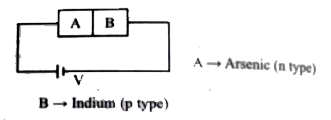
Two sides of a semiconductor germanium crystal A and B are doped with arsenic and indium respectively. They are connected to a battery as shown in figure.
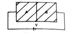
The correct graph between current and voltage for the arrangement is:

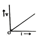
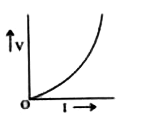
The correct Answer is:A
Topper's Solved these Questions
- SEMICONDUCTOR ELECTRONICS BOOK - PHYSICS WALLAHCHAPTER - SEMICONDUCTOR ELECTRONICS EXERCISE - LEVEL-2
30 Videos
- RAY OPTICS AND OPTICAL INSTRUMENTS BOOK - PHYSICS WALLAHCHAPTER - RAY OPTICS AND OPTICAL INSTRUMENTS EXERCISE - NEET PAST 5 YEARS QUESTIONS
16 Videos
- SYSTEM OF PARTICLES AND ROTATIONAL MOTION BOOK - PHYSICS WALLAHCHAPTER - SYSTEM OF PARTICLES AND ROTATIONAL MOTION EXERCISE - NEET PAST 5 YEARS QUESTIONS
22 Videos
Similar Questions
Two semiconductor materials X and Y, shown in the given, are made by doping germanium crystal with indium and arsenic respectively. The two are joined end to end and connected to a battery as shown.
(i) Will the junction be forward biased or reverse biased ?
(i) Sketch a V-I graph for this arrangement.
View Solution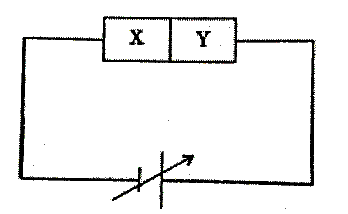
Two semiconductor materials X and Y shown in the given figure, are made by doping germanium crystal with indum and arsenic respectively. The two are joined end to end and connected to a battery as shown.
(i). Will the junction be forward biased or reverse biased.?
(ii). Sketch a V-I graph for this arrangement.
View Solution
Knowledge Check
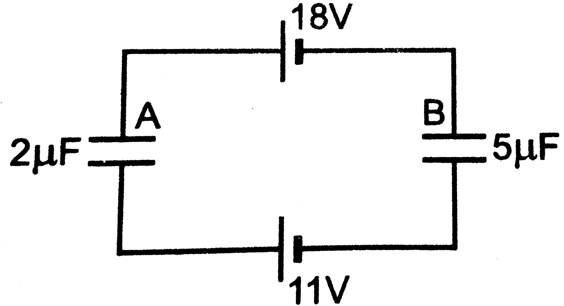
Two capacitors A and B of capacitances 2μF and 5μF are connected to two battery as shown in figure The potential difference in volt between the plate of A is
 A2B5C7D18
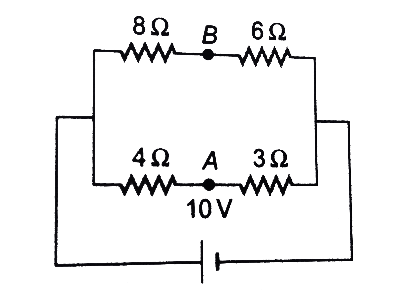
The potential difference between points A and B is
 A2B5C11D18
An ac source of voltage V=Vmsinωt is connected across the resistance R as shown in figure. The phase relation between current and voltage for this circuit is
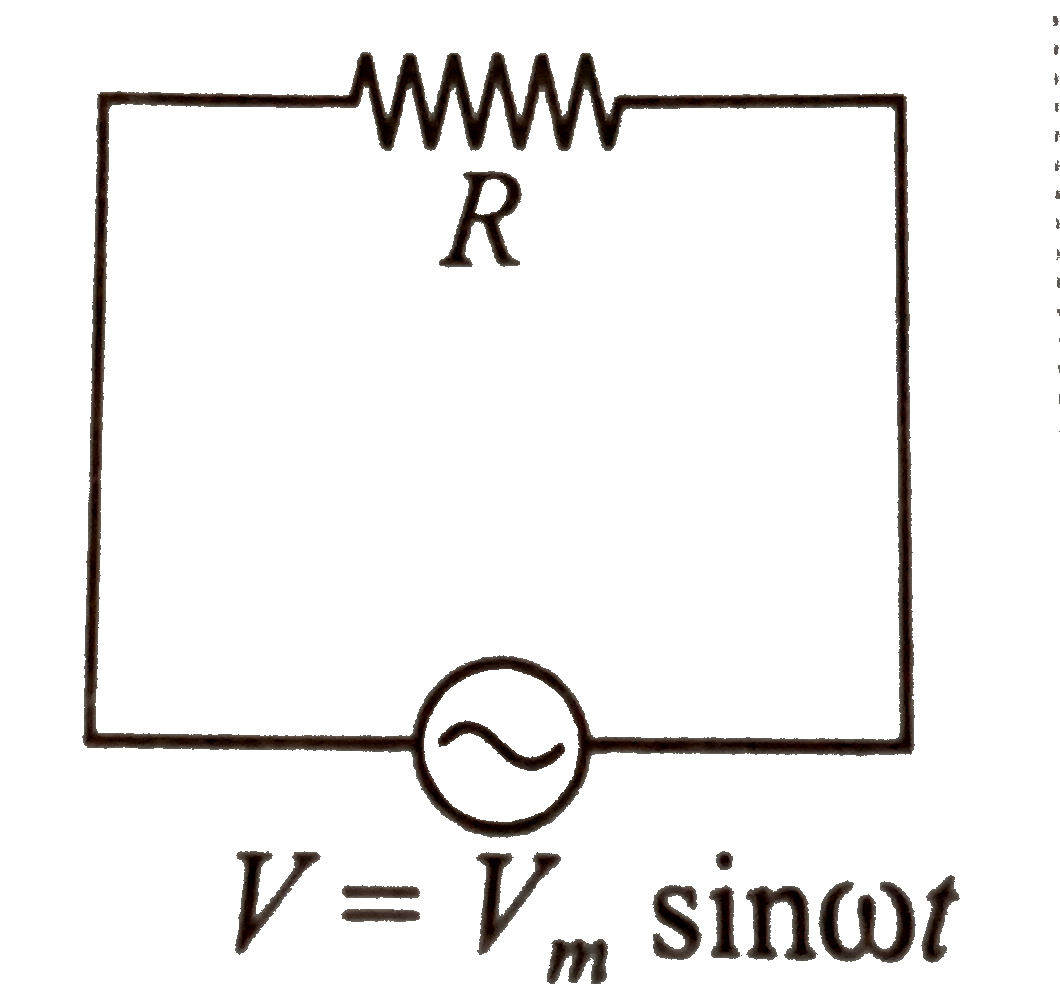 Aboth are in phaseBboth are out of phase by 90∘Cboth are out of phase by 120∘Dboth are out of phase by 180∘
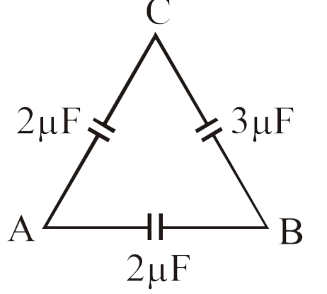
Three capacitors are connected in the arms of a triangle ABC as shown in figure 5 V is applied between A and B. The voltage between B and C is
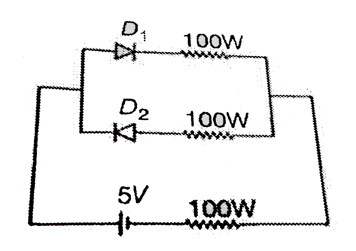
View SolutionTwo ideal diodes D1 and D2 are connected with the battery of 5 volt as shown in figure. Then the current through diode D1 is
View SolutionAn ac source of voltage V=Vmsinωt is connected across the resistance R as shown in figure. The phase relation between current and voltage for this circuit is

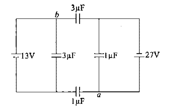
View SolutionFour capacitors and two batteries are connected as shown in the figure. The potential difference between the points a and b is:
View SolutionTwo ideal diodes D1 and D2 are connected with the battery of 5 volt as shown in figure. Then the current through diode D1 is

View Solution
