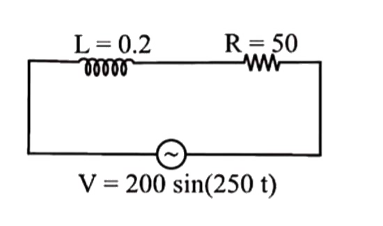
In a LCR series resonating circuit. Give the value of average power loss.
To find the average power loss in an LCR series resonating circuit, we can follow these steps:
1. Understand the Power Loss Formula:
The average power loss P in an LCR circuit can be expressed as:
P=Vrms⋅Irms⋅cosϕ
where Vrms is the root mean square voltage, Irms is the root mean square current, and cosϕ is the power factor.
2. Relate RMS Values to Peak Values:
The RMS values can be related to the peak values as follows:
Vrms=V0√2andIrms=I0√2
where V0 is the peak voltage and I0 is the peak current.
3. Determine the Power Factor:
The power factor cosϕ in an LCR circuit can be expressed as:
cosϕ=RZ
where R is the resistance and Z is the impedance of the circuit.
4. Calculate Impedance at Resonance:
At resonance, the inductive reactance XL equals the capacitive reactance XC:
XL=XC
Therefore, the impedance Z simplifies to:
Z=R
5. Substituting Values into the Power Loss Formula:
Since Z=R at resonance, we can substitute this back into the power loss formula:
P=Vrms⋅Irms⋅RR=Vrms⋅Irms
6. Substituting RMS Values:
Now substituting the RMS values:
P=(V0√2)⋅(I0√2)=V0⋅I02
7. Final Result:
Thus, the average power loss in an LCR series resonating circuit is:
P=V0⋅I02
The average power loss P in an LCR circuit can be expressed as:
P=Vrms⋅Irms⋅cosϕ
where Vrms is the root mean square voltage, Irms is the root mean square current, and cosϕ is the power factor.
The RMS values can be related to the peak values as follows:
Vrms=V0√2andIrms=I0√2
where V0 is the peak voltage and I0 is the peak current.
The power factor cosϕ in an LCR circuit can be expressed as:
cosϕ=RZ
where R is the resistance and Z is the impedance of the circuit.
At resonance, the inductive reactance XL equals the capacitive reactance XC:
XL=XC
Therefore, the impedance Z simplifies to:
Z=R
Since Z=R at resonance, we can substitute this back into the power loss formula:
P=Vrms⋅Irms⋅RR=Vrms⋅Irms
Now substituting the RMS values:
P=(V0√2)⋅(I0√2)=V0⋅I02
Thus, the average power loss in an LCR series resonating circuit is:
P=V0⋅I02
Similar Questions
Knowledge Check
Assertion : In series LCR resonance circuit, the impedance is equal to the ohmic resistance.
Reason : At resonance, the inductive reactance exceeds the capacitive reactance.AIf both assertion ans reason are true ans reaason is the correct explanation of assertion.BIf both assertion and reason are true but reason is not the correct explanation of assertion.CIf assertion istrue but reason is false.DIf both assertion and reason are false.
Refer to the series LCR AC circuit. Find the value of V3

View SolutionIn an LCR circuit, the resonating frequency is 500 kHz. If the value of L is increased two times and value of C is decreased 18 times, then the new resonating frequency in kHz will be -
View SolutionIn LCR circuit during resonance
View SolutionA voltage V=V0sinωt is applied to a series LCR circuit. Derive expression for the average power dissipated over a cycle.
Under What condition (i) no power is dissipated even though the current flows through the circuit?
(ii) Maximum power is dissipated in the circuit?
View SolutionAnswer the following:
(a) Explain the term 'Sharpness of resonance' in ac circuit.
(b) In a series LCR circuit , VL=VC≠VR. What is the value of power factor for this circuit?
View SolutionIn a series resonant LCR circuit the voltage across R is 100 volts and R = 1k(Ω)withC=2(μ)F. The resonant frequency (ω) is 200rad/s. At resonance the voltage across L is
View SolutionIn series LCR circuit at resonance
View Solution

