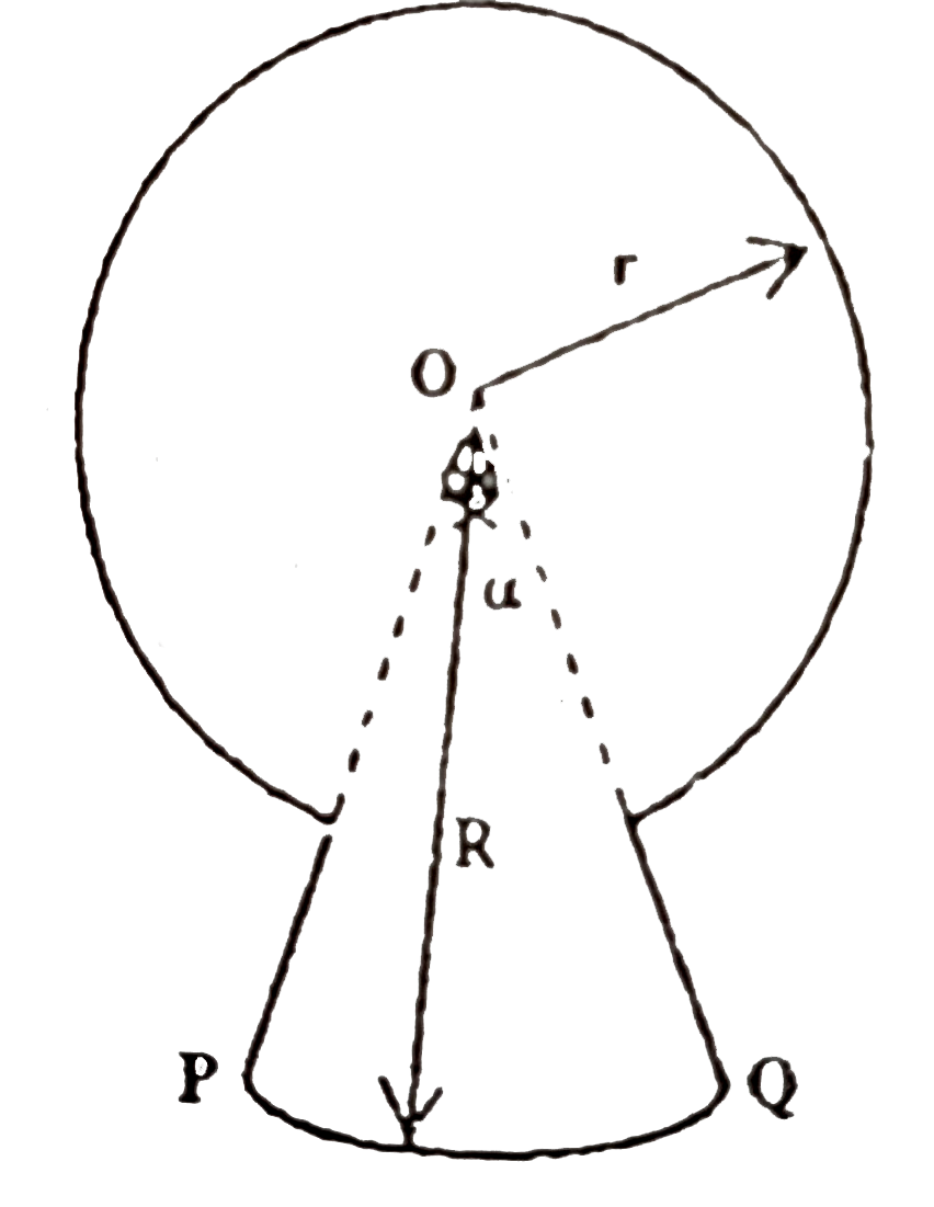
Only circular part of the wire shown in the figure has resistance σ per unit length. The radii of the circles are r and R and ∠POQ=α (in radian). If a potential difference VP−VQ=V is applied across the point P and Q, the magnetic field at point O is
μ04πVσ[2π−αr2−αR2]
μ0V4π[αr2−2π−αR2]
μ04πVσ[1r2−1R2]
μ04πσV[1r2−1R2]
iR=VαRσ(ccw)ir=V(2π−α)rσ(cw)
Similar Questions
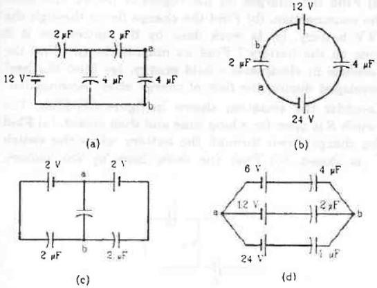
Find the potential difference Va−Vb , between the points a and b shown in each part of the figure.

View SolutionFind the potential difference Va−Vb between the points a and b shown in each part of the figure.
View SolutionAre the points P,Q,R shown in the figure given below collinear ?

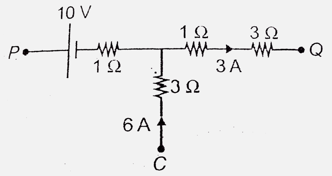
View SolutionThe given circuit is the part of a certain circuit. The current through resistors are shown . The potential difference VP−VQ is
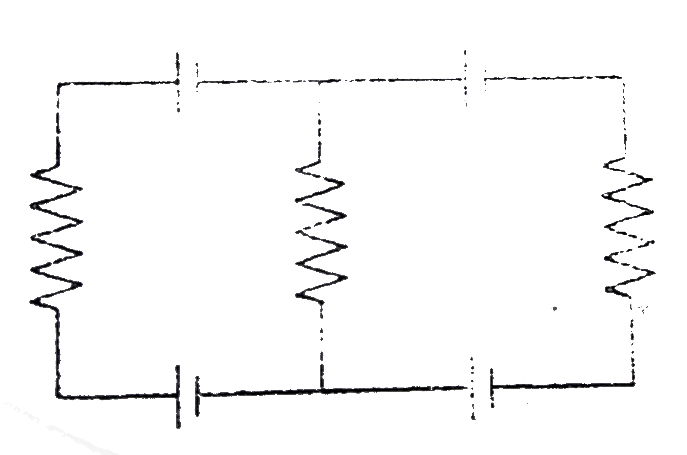
View SolutionEach of the batteries shown in figure has an emt equal to 10V.Find the magnetic field B at the point p.
View SolutionThe potential difference (V−PVundersetQ) between the points P nad Q in the part of a circuit as shown in figure is
_PHY_E05_026_Q01.png)
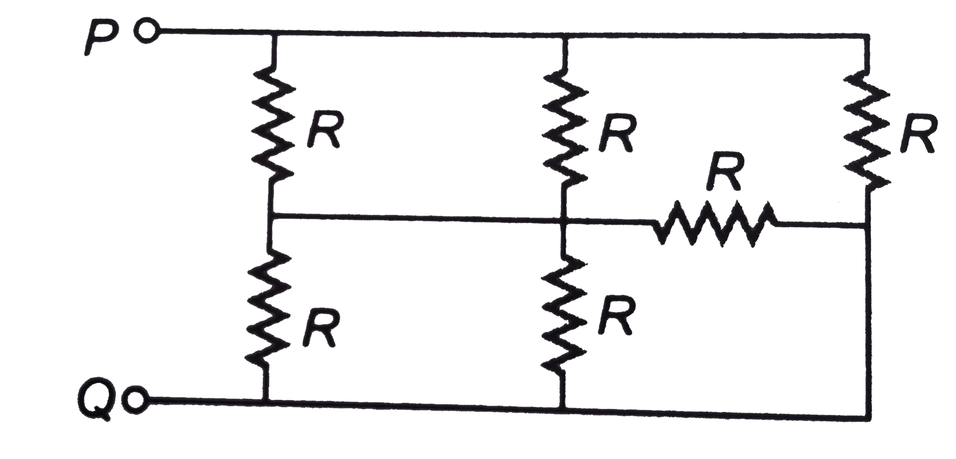
View SolutionIn the circuit shown in figure R=55Ω the equivalent resistance between the point P and Q is
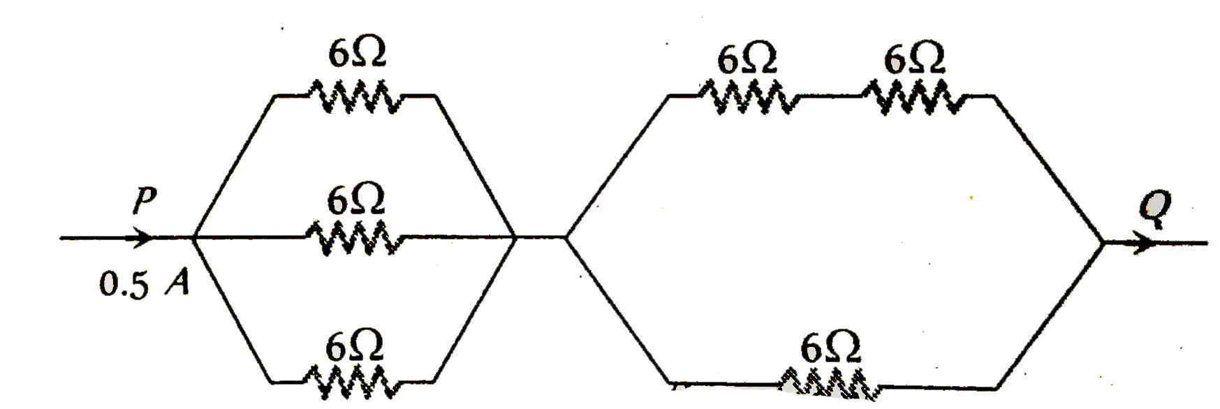
View SolutionResistances of 6 ohm each are connected in the manner shown in adjoining figure. With the current 0.5 ampere as shown in figure, the potential difference VP−VQ is
View SolutionIn the part of a circuit shown in figure, the potential different
(VG−VH) between points G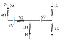
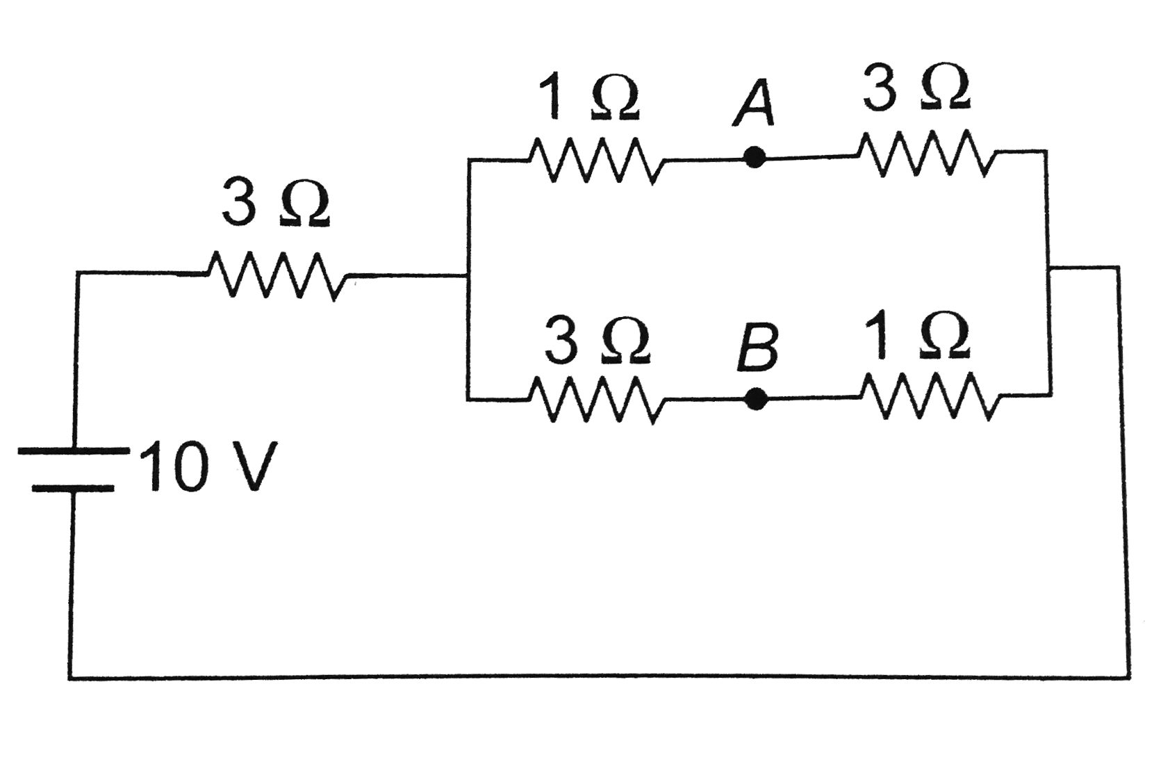
View SolutionA battery of e.m.f. 10V is connected to resistance as shown in figure. The potential difference VA−VB between the point A and B is
View Solution
