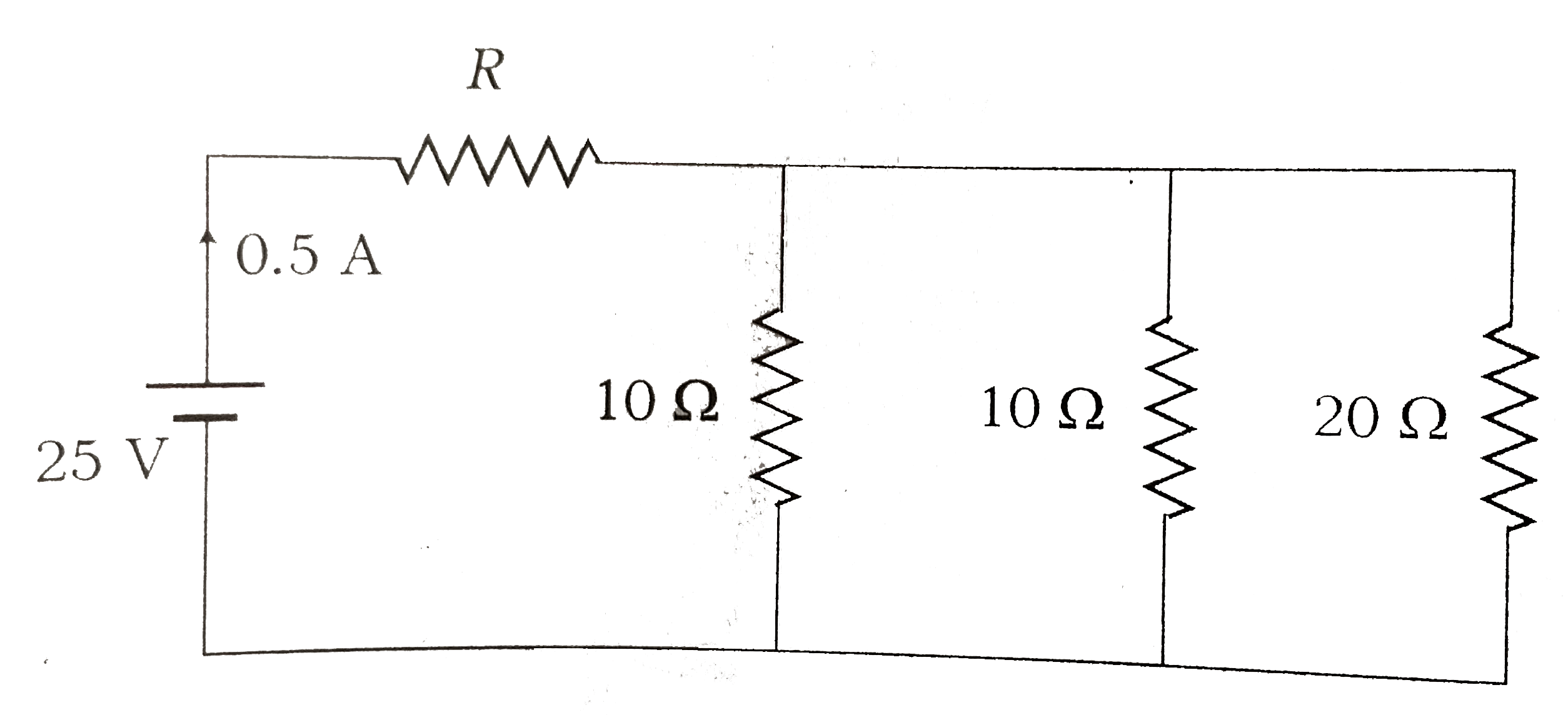
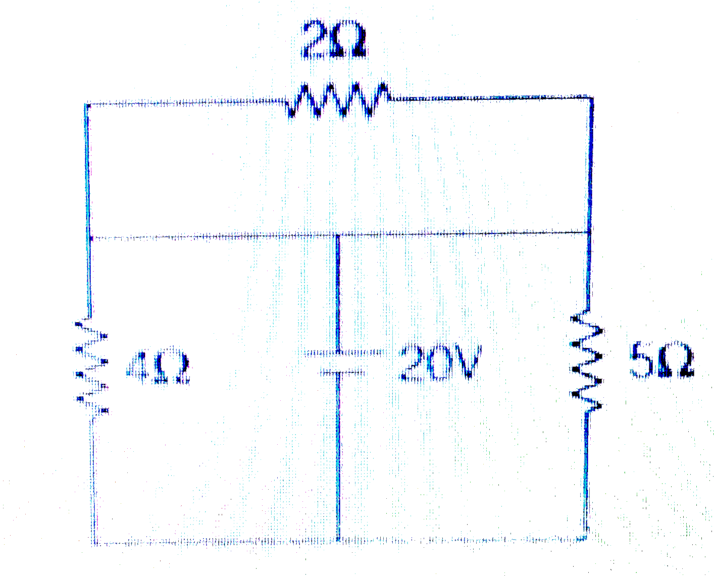
For the circuit shown in figure,
A
resistance R=46Ω
B
current through 20Ω resistance is 0.1A
C
potential difference across the middle resistance is 2 V
D
All of the above are true
Video Solution
Text Solution
The correct Answer is:D
|
Answer
Step by step video & image solution for For the circuit shown in figure, by Physics experts to help you in doubts & scoring excellent marks in Class 12 exams.
Updated on:21/07/2023Topper's Solved these Questions
- CURRENT ELECTRICITYBOOK - DC PANDEY ENGLISHCHAPTER - CURRENT ELECTRICITYEXERCISE - Match the columns
4 Videos
- COMMUNICATION SYSTEMBOOK - DC PANDEY ENGLISHCHAPTER - COMMUNICATION SYSTEMEXERCISE - Subjective
11 Videos
- ELECTROMAGNETIC INDUCTIONBOOK - DC PANDEY ENGLISHCHAPTER - ELECTROMAGNETIC INDUCTIONEXERCISE - Medical entrances gallery
25 Videos
Similar Questions
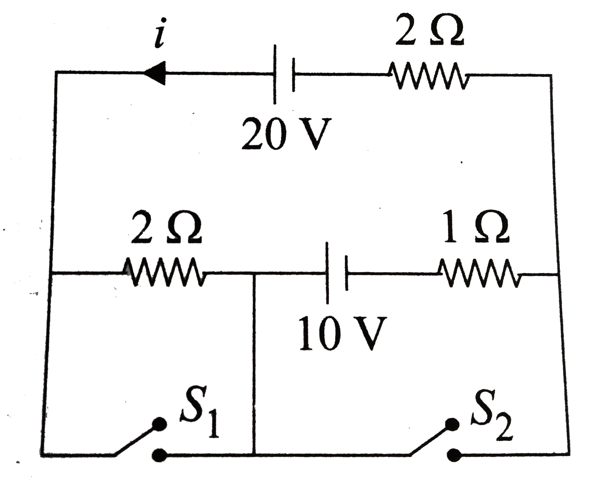
In the circuit shown in figure,
View SolutionIn the circuit shown in figure
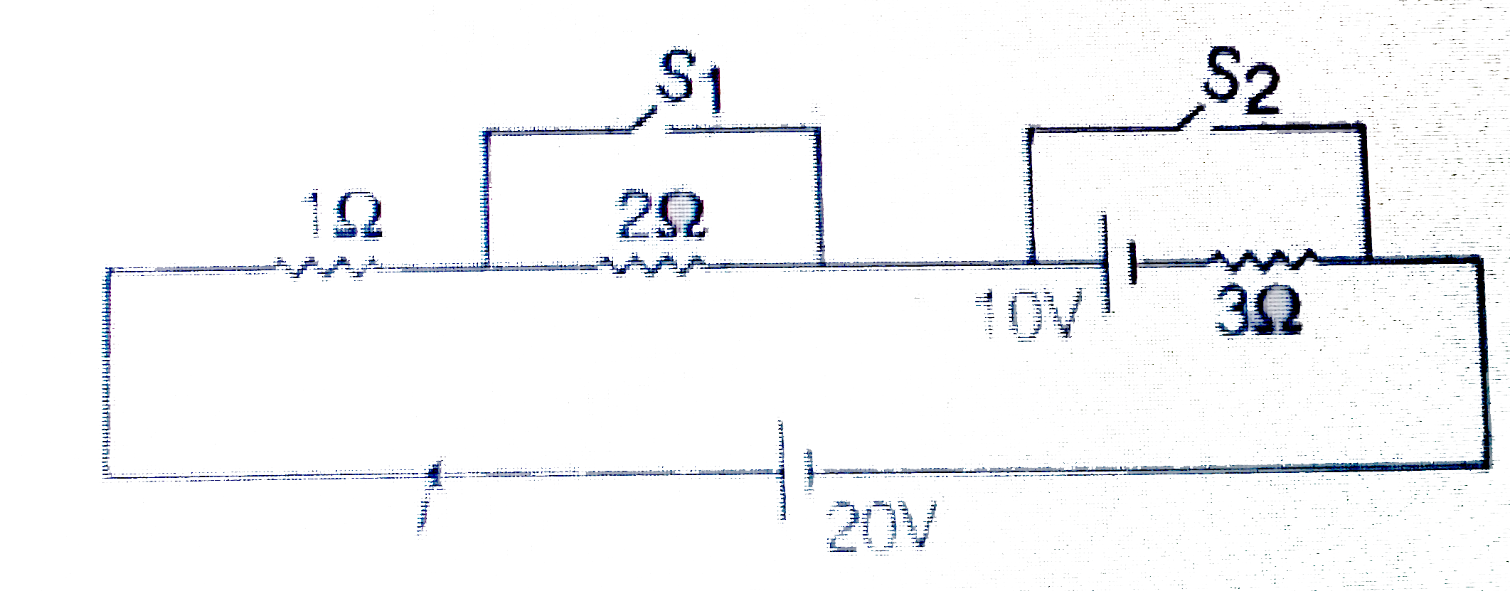
View SolutionIn the circuit shown in figure
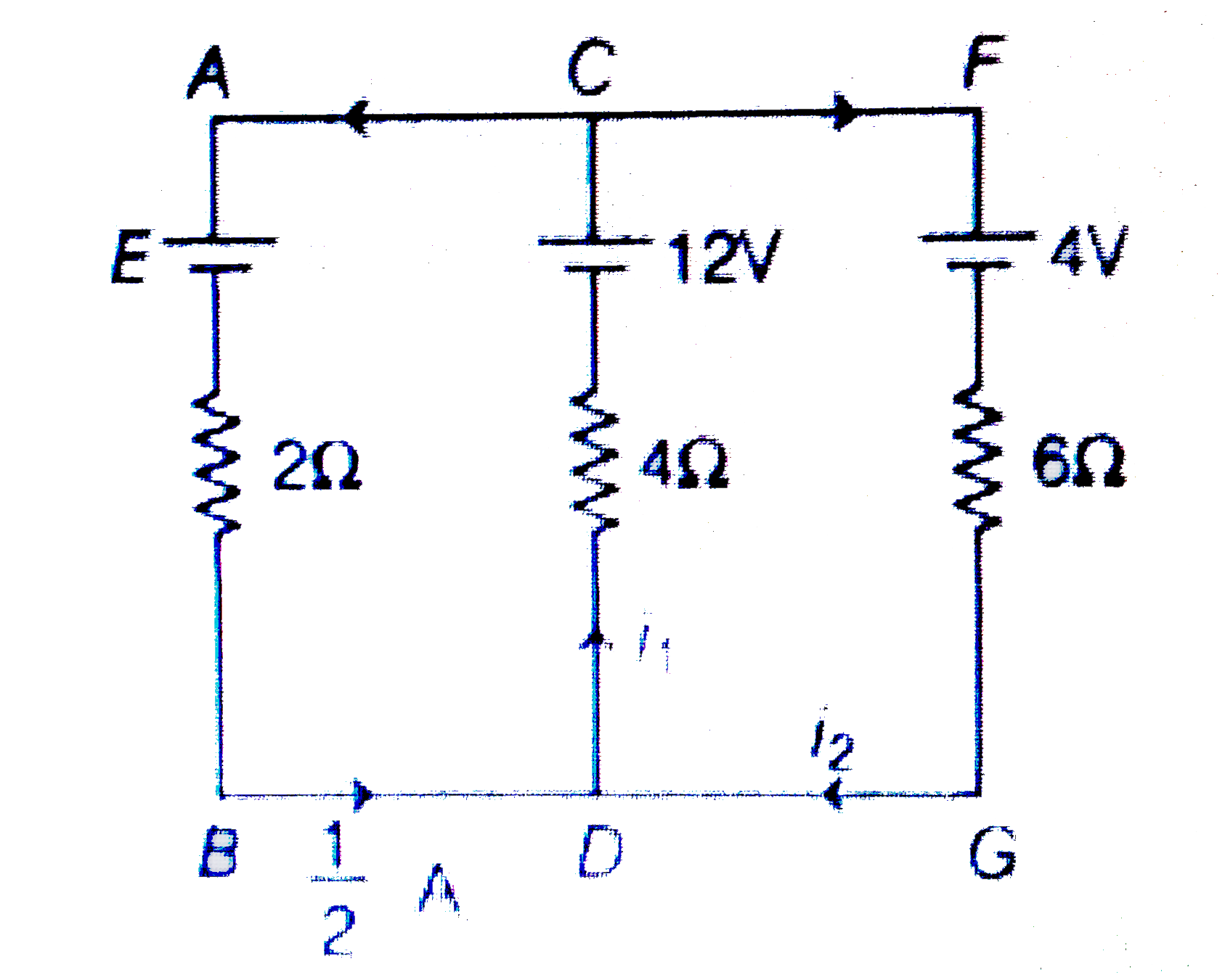
View SolutionIn the circuit shown in figure
View SolutionIn the circuit shown in figure
View SolutionIn the circuit shown in figure
View SolutionIn the circuit shown in figure
View SolutionIn the circuit shown in figure
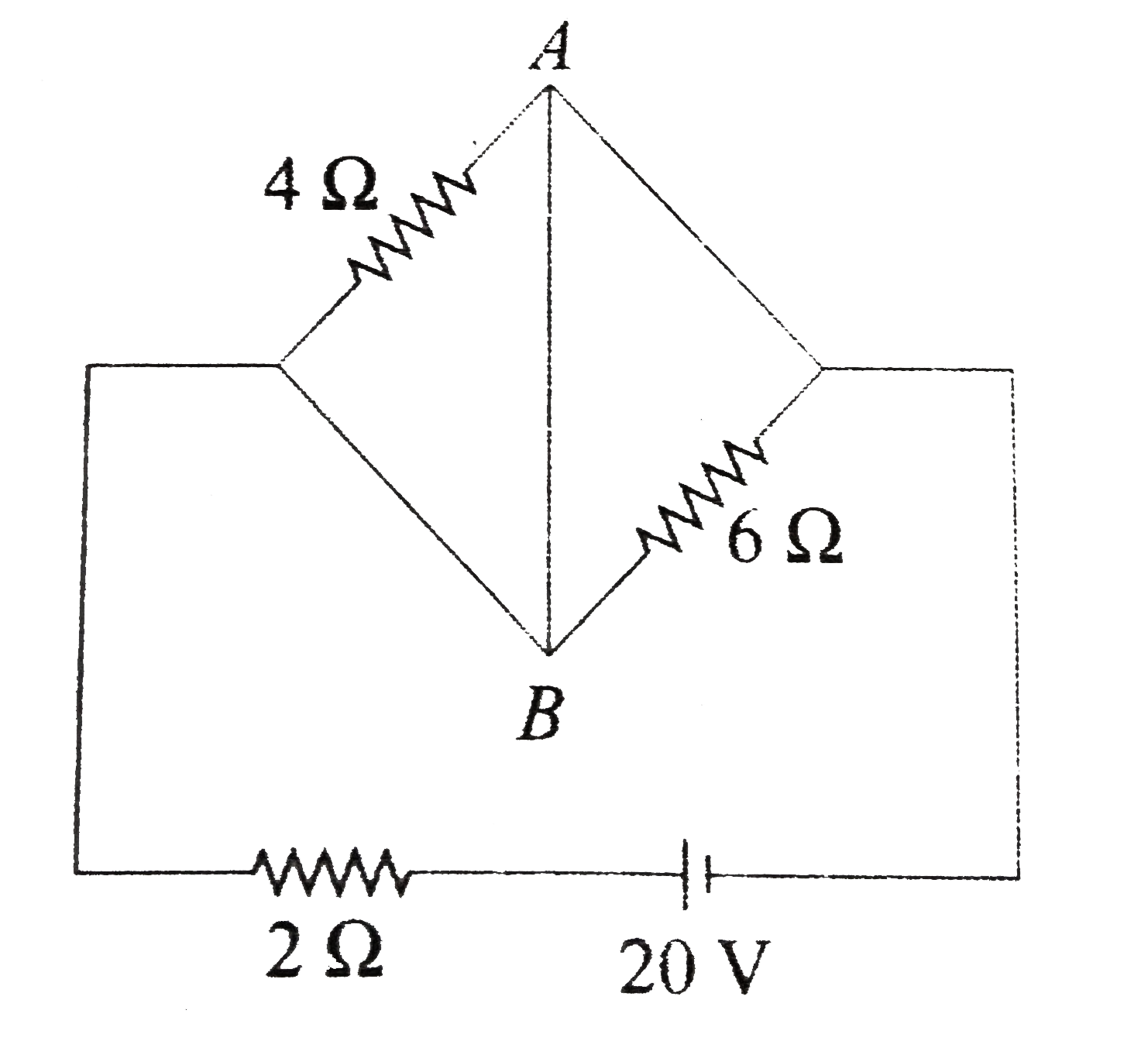
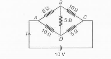
View SolutionIn the circuit shown in figure, the current / in circuit is
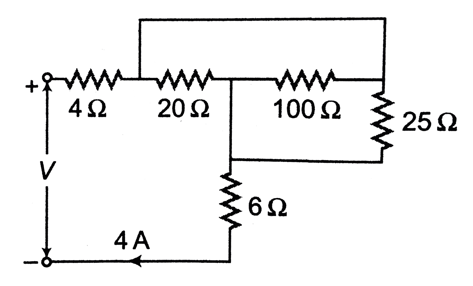
View SolutionIn the circuit shown in figure , V must be
View Solution
