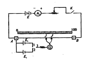
Draw a circuit diagram for the expression of e. m.f.'s of two primary cells using a potentiometer.
It works on the principle, that Potential difference across any part of a uniform wire is directly proportional to the length of that portion, when a constant current flows through the wire.
Let, I= length of the wire,
R= resistance of the wire,
I= current flowing through the wire,
V= potential difference across the wire
A= area of cross-section of wire
ρ= resistivity of wire.
Then, from Ohm.s law, V=IR
But, R=ρlA ∴V=IρlA(IρA)I
Since IρA= constant (K) ∴V=KI or V∝I,
Which is the principle of Potentiometer. The desired circuit diagram is shown in the following figure : Connect a battery E, key K, ammeter A1 and rheostat between A and B.
The positive terminals of the two cells E1andE2 whose emfs are to be compared are connected to a point A of the potentiometer wire. Their negative terminals are connected to terminals (1) and (2) of the two way key. The terminal (3) of the two way key is connected to jockey J through a galvanometer G. Close the key K and with the help of rheostat adjust a constant current in the potentiometer wire.
Connect terminals (1) and (3) of the two way key. Due to this, the cell E1 comes in the circuit and the galvanometer G gives deflection. Move the jockey on the wire. A position J is reached when galvanometer shows nill deflection. Note down AJ. Let AJ=I1
Then from the principle of the potentiometer,
E1αI1⇒E1=kl1 .......(i)
Now disconnect terminals (1) and (3) and connect the terminals (2) and (3) of the two way key. Due to this the cell E2 comes in the circuit and the galvanometer G shows some deflection. Now move the jockey on the wire. A position J is reached, when the galvanometer shows null deflection. Note down AJ and Let AJ =I2
Then E2αI2⇒E2=kI2 ........(ii)
Dividing equation (i) by (ii), we get E1E2=kI1kI2⇒E1E2=I1I2
Similar Questions
Draw a circuit diagram for the determination of the internal resistance of a cell using potentiometer. Derive the formula to be used.
View SolutionState the principle of potentiometer. Draw a circuit diagram used to compare the emfs of two primary cells. Write the formula used. How can the sensitivity of a potentiometer be increased.
View Solution
Knowledge Check
Correct diagram for the determination of internal resistance of a primary cell by potentiometer
A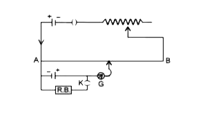 B
B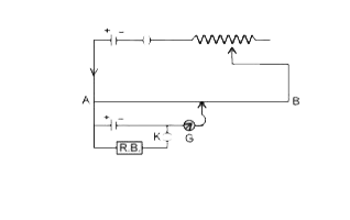 C
C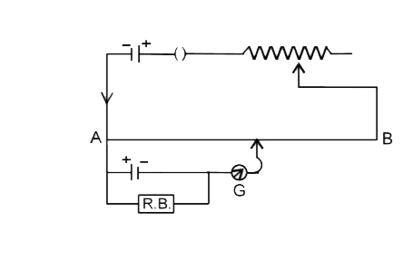 DNone of the above
The following diagram shows the circuit for the comparision of e.m.f. of the cells. The circuit can be corrected by:-
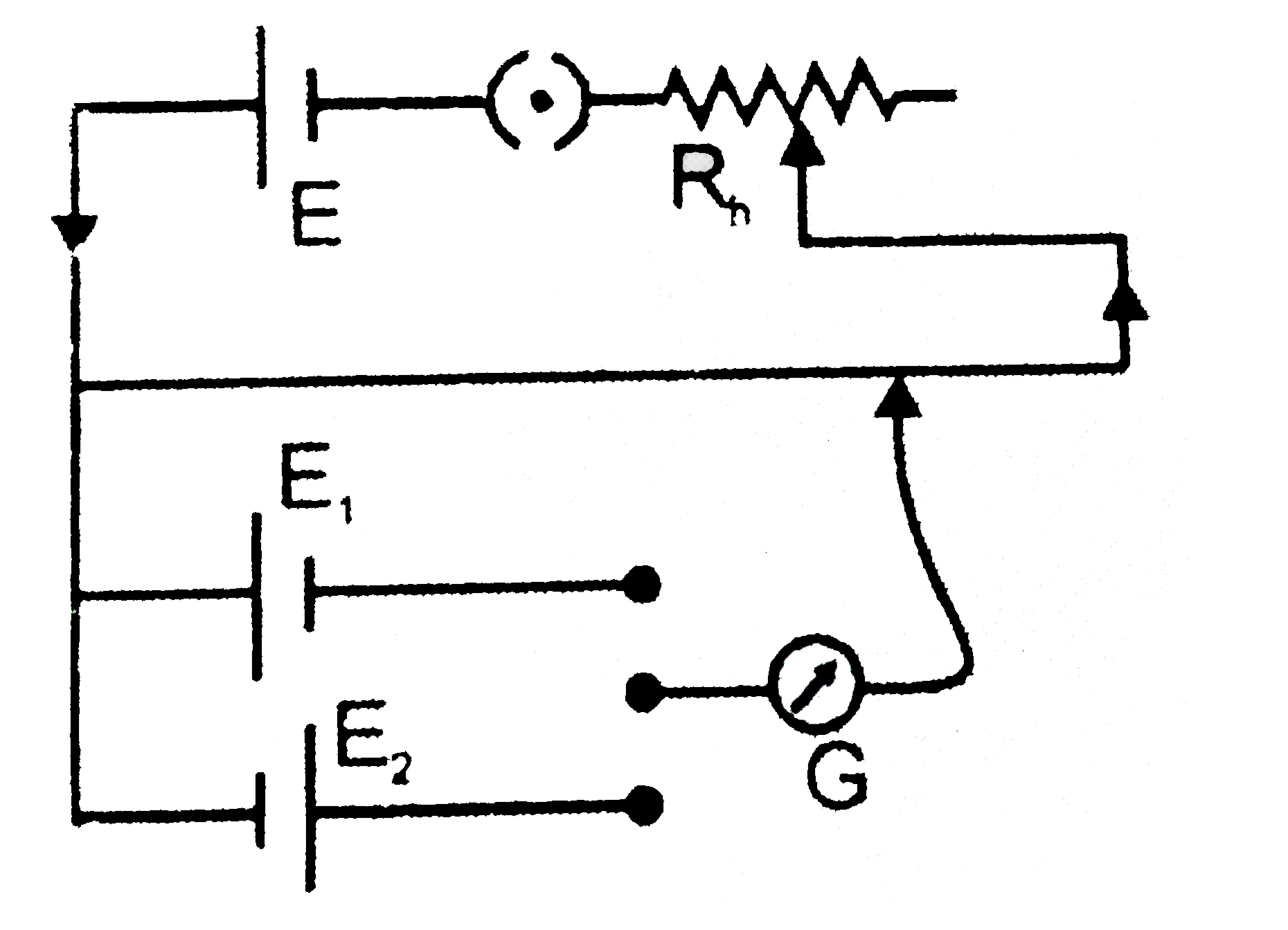 AReversing the terminals of EBReversing the terminals of E1CReversing the terminals E2DReversing the current in Rh.
The internal resistance of a cell by potentiometer is given by
View SolutionThe following diagram shows the circuit for the comparision of e.m.f. of the cells. The circuit can be corrected by:-

View SolutionThe following diagram shows the circuit for the comparision of e.m.f. of the cells. The circuit can be corrected by:-

View SolutionDraw a labelled circuit diagram of a potentiometer to compare emfs of two cells. Write the working formula (Derivation not required).
View SolutionState the working principle of a potentiometer. With the help of the circuit diagram explain how a potentiometer is used to compare the emfs of two primary cells. Obtain the required expression used for comparing the emfs.
View Solution(a) State the working principle of a potentiometer. With the help of the circuit diagram, explain how a potentiometer is used to compare the emfs of two primary cells. Obtain the required expression used for comparing the emfs.
(b) Write two possible causes for one sided deflection in a potentiometer experiment.
View Solution
