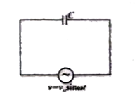
An alternate e.m.f. is applied to pure capacitance . Investigate the phase relationship between the current flowing through it and e.m.f. applied
Let us consider that an alternating e.m.f.v=vmsinωt is applied to a pure capacitor of capacitance C as shown in the figure
v=vmsinωt . . . (i)
Let .q. be the change on the capacitor at any instant, then the potential difference across the
capacitor vc=qC
But vc=v
Substituting in eqn.(i) , we get qC=vmsinωt
⇒q=Cvmsinωt
Also i=dqdt=ddt(Cvmsinωt)
⇒i=Cvmddt(sinωt)=Cvm(cosω)ω
⇒i=vm1Cωcosωt

⇒i=vm1Cωsin(ω+π2) [ ∴cosωt=sin(ωt+π2)]
where im=vm1Cω is the peak value of alternating current 1Cω=XC is known as capacitive reactance of the capacitor
From equation (i) and (ii) it is clear that current leads the induced e.m.f. by an angle of π2 . Time and phasor diagrams are shown in the figure 
Average power in purely capacity circuit
P=VrmsIrmscosϕ
here ϕ=π2∴P=VrmsIrmscosπ2=0
Similar Questions
Discuss the phase relationship between current and emf in an circuit containing a capacitance only.
View SolutionExplain the term 'capacitive reactance'.Show graphically the variation of capacitive reactance with frequency of the applied alternating voltage.
An a.c. voltage E=E0sinωt is applied a across a pure capacitor C.Show mathematically that the current flowing through it leads the applied voltage by a phase angle of π/2
View Solution
Knowledge Check
An alternating e.m.f. is applied to purely capacitive circuit. The phase relation between e.m.f. and current flowing in the circuit is or in a circuit containing capacitance only
Ae.m.f. is ahead of current by π/2BCurrent ahead of e.m.f by π/2CCurrent lags behind e.m.f. by πDCurrent is ahead of e.m.f. by πIf an alternating e.m.f. is applied to a series L-R circuit, the phase angle between e.m.f. and current is given by tanθ=ωLR. Hence the power factor of the series L-R circuit is
A1. ωLRB2. RωLC3. RR+ωLD4.R√R2+ω2L2The phase angle between e.m.f. and current in LCR series ac circuit is
A0 to π/2Bπ/4Cπ/2Dπ
Explain the term 'capacitive reactance'.Show graphically the variation of capacitive reactance with frequency of the applied alternating voltage.
An a.c. voltage E=E0sinωt is applied a across a pure capacitor C.Show mathematically that the current flowing through it leads the applied voltage by a phase angle of π/2
View SolutionExplain the term 'inductive reactance'.Show graphically the variation of inductive reactance with frequency of the applied alternating voltage.
An a.c. voltage E=E0sinωt is applied across a pure inductor L.Show mathematically that the current flowing through it lags behind the applied voltage by a phase angle of π/2.
View SolutionAn alternating e.m.f. 100 cos 100 t volt is connected in series to a resistance of 10 ohm and inductance 100mH. The phase difference between the current in the circuit and the e.m.f. is
View SolutionAn alternating e.m.f. 100 cos 100 t volt is connected in series to a resistance of 10 ohm and inductance 100mH. The phase difference between the current in the circuit and the e.m.f. is
View Solution
