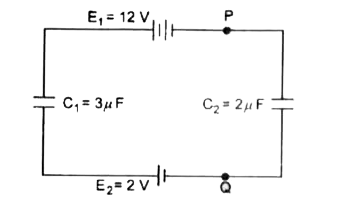
The potential difference between points P and Q in the circuit shown is Fig. is :
A
6 V
B
2 V
C
10 V
D
14 V
Text Solution
The correct Answer is:A
Effective voltage in circuit (E)=E1−E2=10V
∴ Cs=C1C2C1+C2=1.2μF
∴Q= Charge on capacitors = CsV
=1.2μF×10V
=12μF
∴ P.D across P and Q = 12μC12μF=6V
|
Topper's Solved these Questions
- ELECTROSTATICSBOOK - MODERN PUBLICATIONCHAPTER - ELECTROSTATICSEXERCISE - LEVEL -II
74 Videos
- ELECTROSTATICSBOOK - MODERN PUBLICATIONCHAPTER - ELECTROSTATICSEXERCISE - LEVEL-III
23 Videos
- ELECTRONS & PHOTONSBOOK - MODERN PUBLICATIONCHAPTER - ELECTRONS & PHOTONSEXERCISE - RECENT COMPETITIVE QUESTIONS
20 Videos
- GRAVITATIONBOOK - MODERN PUBLICATIONCHAPTER - GRAVITATIONEXERCISE - Recent Competitive Questions
8 Videos
Similar Questions
Knowledge Check
The potential difference between points A and B in the circuit shown in fig. 5.317 is 16V. Then
 Athe current through the 2Ω resistance is 3.5ABthe current through 4Ω resistance is 2.5ACthe current through 3Ω resistance is 1.5ADthe potential difference between the terminals of the 9V battery is 7V
The potential difference between points A and B in the circuit shown in figure will be
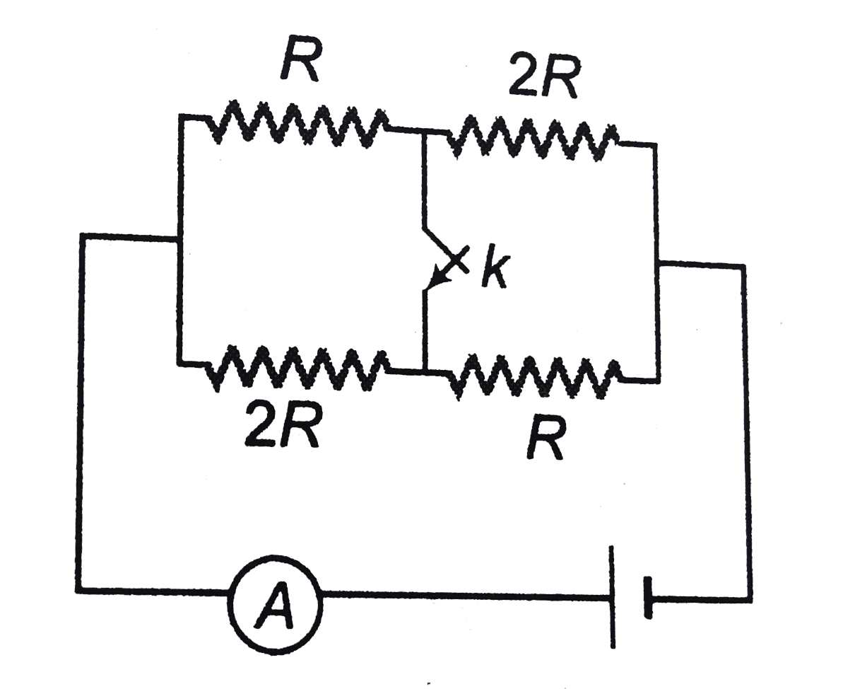 A1VB2VC−3VDnone of these
The potential difference between points a and b of circuits shown in figure is
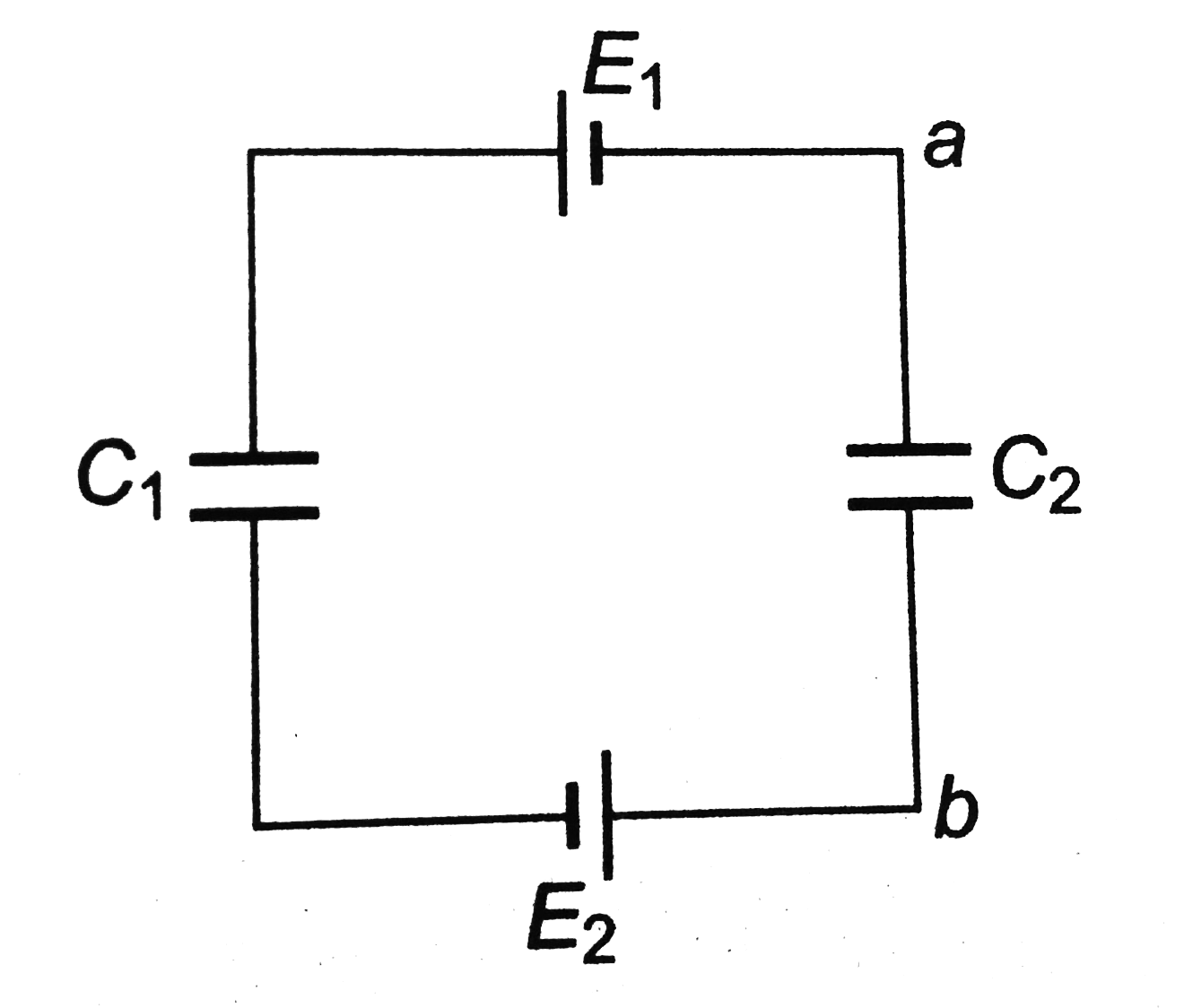 A(E1+E2C1+C2)C2B(E2−E2C1+C2)C2C(E1+E2C1+C2)C1D(E1−E2C1+C2)C1
The potential difference between points a and b of circuits shown in figure is

View SolutionWhat is the potential difference between points A and B in the circuit shown?
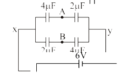
View SolutionWhat is the potential difference between points A and B in the circuit shown?

View SolutionThe potential difference between A and B in the circuit shown is -
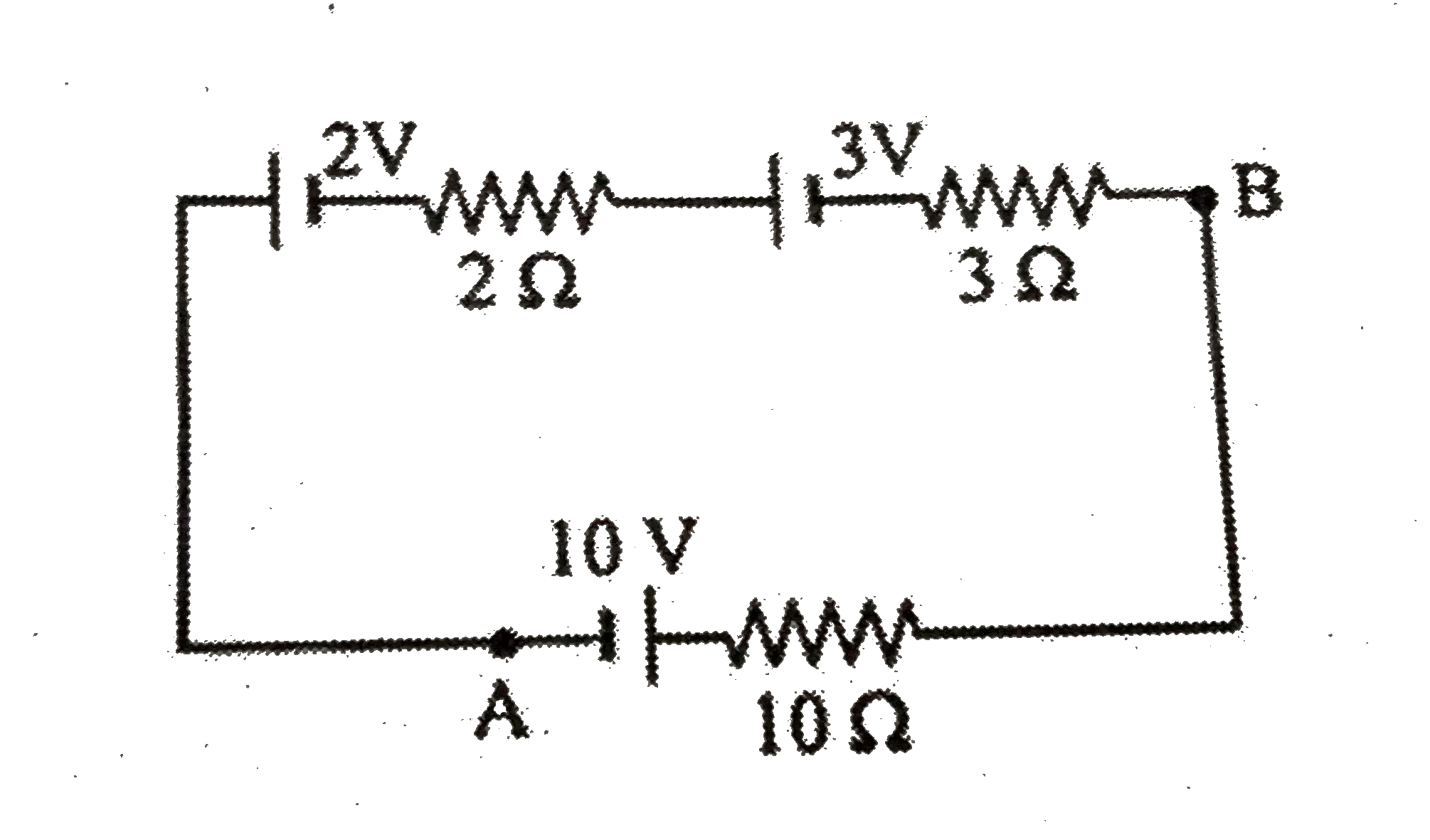
View SolutionThe potential difference between points A and Bin the circuit shown in figure-3.318, will be:
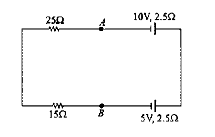
View Solution
