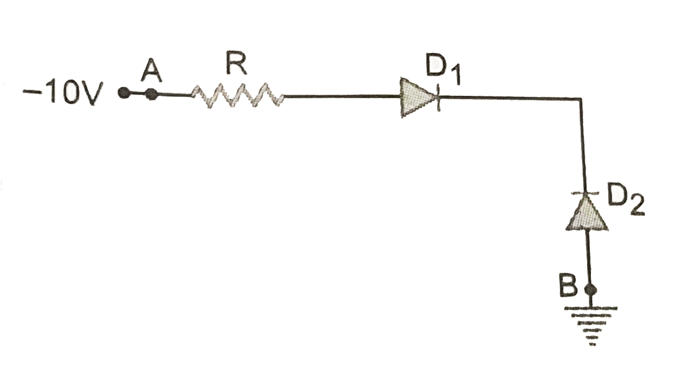
In Figure, assuming the diodes to be ideal,
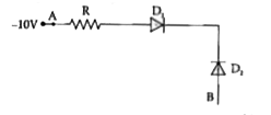
D1 is forward biased and D2 is reverse biased and hence current flows from A to B
D2 is forward biased and D1 is reverse biased and hence no current flows from B to A and vice versa.
D1 and D2 are both forward biased and hence current flows from A to B.
D1 and D2 are both reverse biased and hence no current flows from A to B and vice versa.
The correct Answer is:B
In circuit A is at -10 V and B is at 0 V. So B is positive than A. So D2 is in forward bias and D1 is in reverse bias, so no current flows from A to B or B to A.
Similar Questions
Knowledge Check
In Fig assuming the diodes to be ideal :
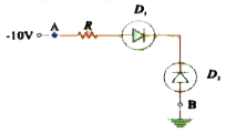 AD1 is forward biased and D2 is reverse biased and hence current flow form A to BBD2 is forward biased and D1 is reverse biased and hence no current flows from B to A and vice versaCD1andD2 are both forward biased and hence current flows from A to BDD1andD2 are both reverse biased and hence no current flows from A to B and vice-versa
In Fig.assuming the diode to be ideal
 AD1 is forward biased and D2 is reverse biased and hence current flows from A to BBD2 is forward biased and D1 is reverse biased and hence no current flows from B to A and vice versaCD1 and D2 are both forward biased and hence current flows from A to BDD1 and D2 are both reverse biased and hence no current flows from A to B and vice versa
In a figure given alongside assuming the diodes to be ideal
 AD1 is forward biased and D2 is reverse biased and hence, current flows from A to BBD2 is forward biased and D1 is reverse biased and hence, no current flows from B to A and vice-versaCD1 and D2 are both forward biased and hence current flows from A to BDD1 and D2 are both reverse biased and hence no current flows from A to B and vice-versa
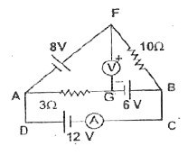
Find the reading of ammeter A and voltmeter V shown in the figure assuming the instruments to be ideal
View SolutionIn the circuit shown below, assume the diode to be ideal. When Vi increases from 2 V to 6 V, the change in the current in (in mA)

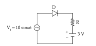
View SolutionChoose the correct waveform that can represent the voltage across R of the following circuit, assuming the diode is ideal one :
View SolutionThe figure below shows a circuit and its input voltage vi as function of time t.
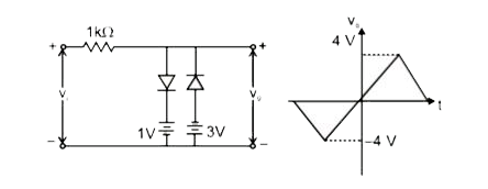
Assuming the diodes to be ideal, which of the following graphs depicts the output voltage v0 as function of time t ?
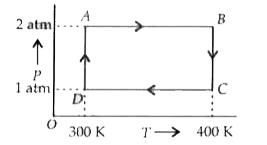
View SolutionTwo moles of helium gas undergo a cyclic process as shown in figure. Assuming the gas to be ideal. The net work done by the gas is
View Solution

