In the circuit shown in Fig., the cell is ideal with e.m.f = 2V. The resistance of the coil of the galvanometer G is 1Ω. Then
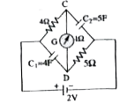
initially no current flows in G
in steady state 0.2 A current flows in G
potential difference across C1 is 1V
potential difference across C2 is 1.2 V
The correct Answer is:B, C, D
Step by step video & image solution for In the circuit shown in Fig., the cell is ideal with e.m.f = 2V. The resistance of the coil of the galvanometer G is 1Omega. Then by Physics experts to help you in doubts & scoring excellent marks in Class 12 exams.
Updated on:21/07/2023Topper's Solved these Questions
- CURRENT ELECTRICITYBOOK - AAKASH SERIESCHAPTER - CURRENT ELECTRICITYEXERCISE - PRACTICE SHEET (EXERCISE - VII LEVEL-II (ADVANCED) (Integer Type Questions))
1 Videos
- CURRENT ELECTRICITYBOOK - AAKASH SERIESCHAPTER - CURRENT ELECTRICITYEXERCISE - ADDITIONAL PRACTICE EXERCISE (LEVEL -I(MAIN) (Straight Objective Type Questions))
20 Videos
- CURRENT ELECTRICITYBOOK - AAKASH SERIESCHAPTER - CURRENT ELECTRICITYEXERCISE - PRACTICE SHEET (EXERCISE - VII LEVEL-II (ADVANCED) (Straight Objective Type Questions))
4 Videos
- CURRENT ELECTRICITYBOOK - AAKASH SERIESCHAPTER - CURRENT ELECTRICITYEXERCISE - PROBLEMS (LEVEL-II)
27 Videos
- DUAL NATURE OF RADIATION AND MATTERBOOK - AAKASH SERIESCHAPTER - DUAL NATURE OF RADIATION AND MATTEREXERCISE - PRACTICE EXERCISEX
42 Videos
Similar Questions
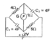
In the circuit shown below the cell is ideal, with emf = 2 V: The resistance of the coil of the galvanometer G is 1Ω. Then, find the potential difference across C1 (in volts), in steady state
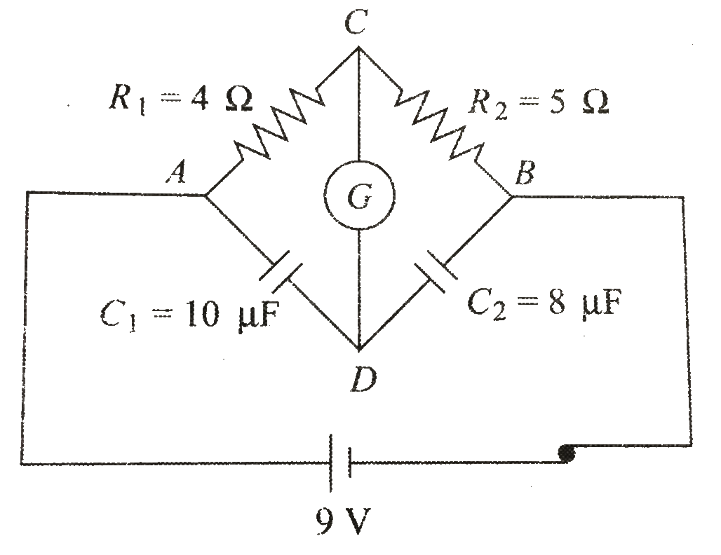
View SolutionIn the circuit shows in Fig. 6.63, the cell is ideal with emf 9V. If the resistance of the coil of galvanometer is 1Ω, then
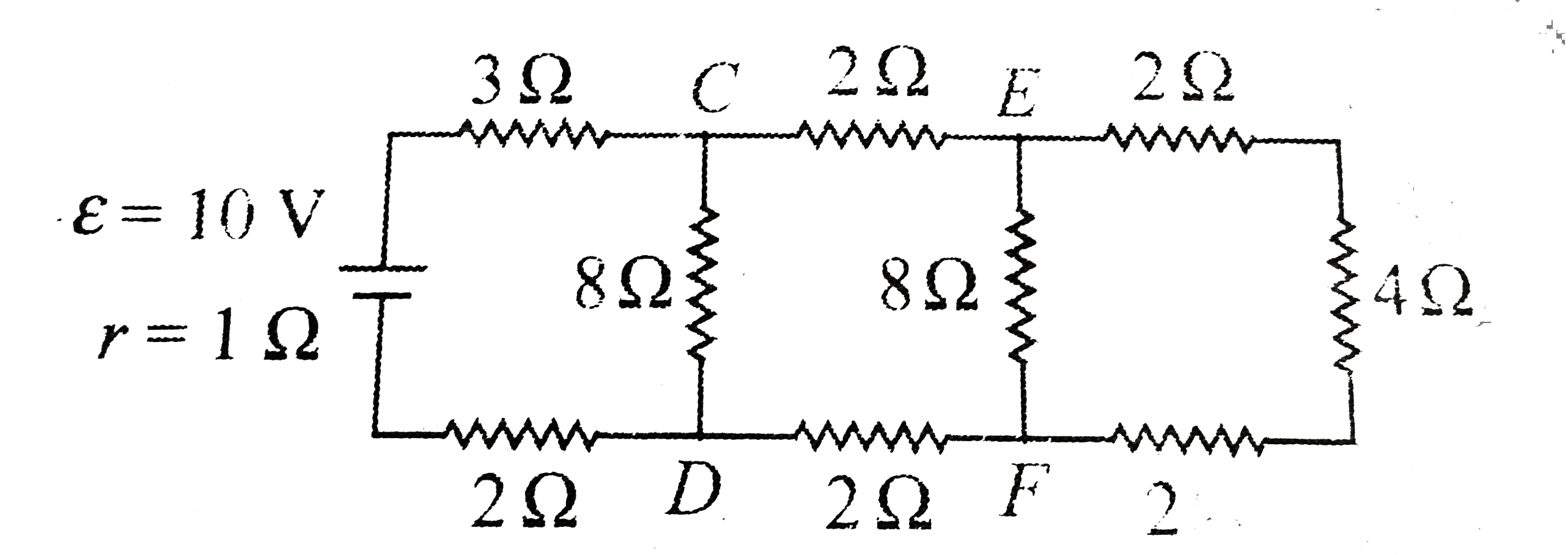
View SolutionIn the circuit shown in fig. the cell has emf 10V and internal resistance 1Ω
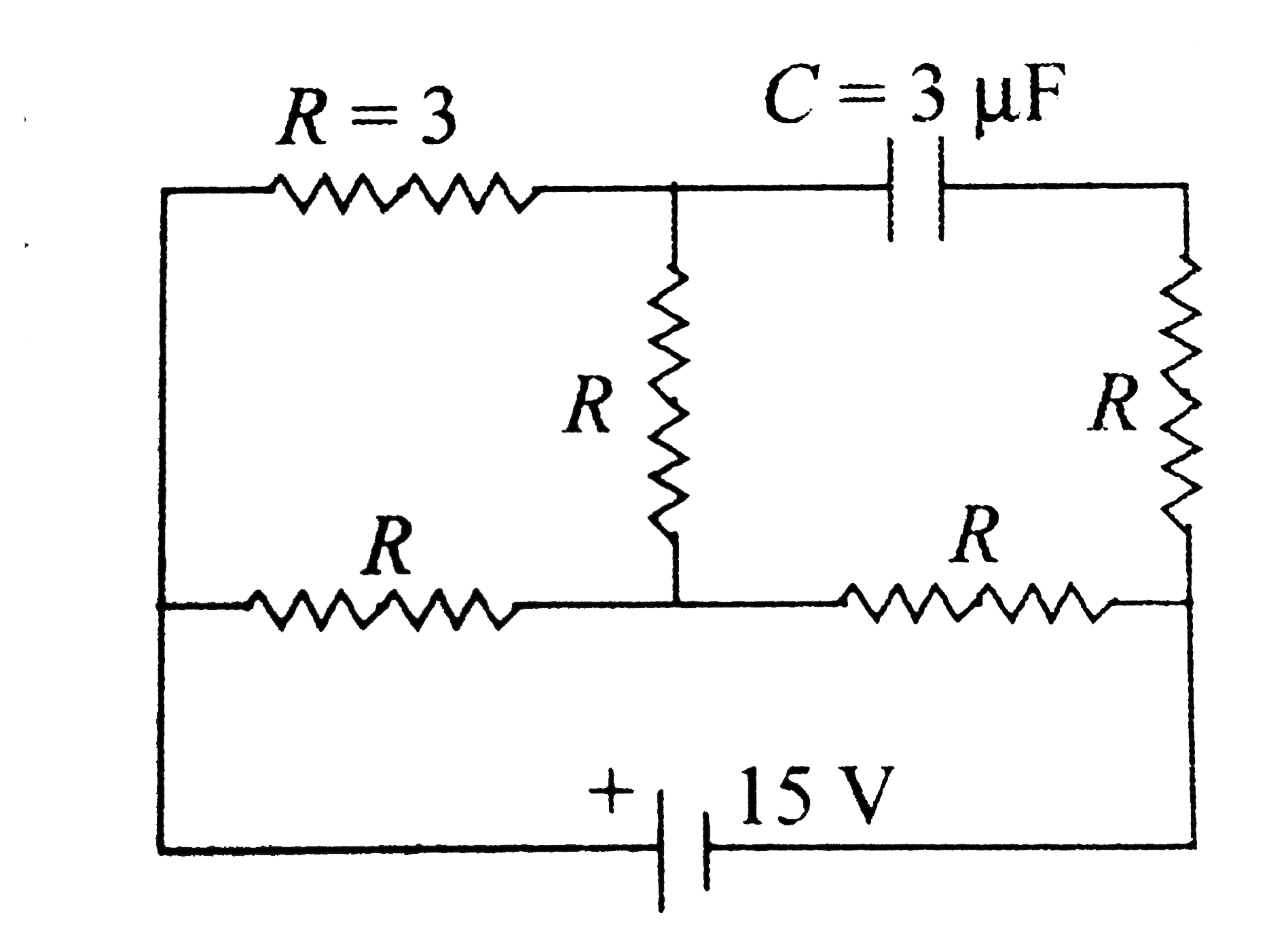
View SolutionIn the circuit shown in fig. the cell is ideal with emf 15V. Each resistance is of 3Ω. The potential difference across the capacitoro in steady state is
View SolutionConsider the circuit shown in the figure, the cell is ideal. The readings of the ideal voltmeters V1 and V2 in volts are respectively.

View SolutionIn the circuit shown in Fig. the emf of the sources is equal to ξ=5.0V and the resistances are equal to R1=4.0Ω and R2=6.0Ω. The internal resistance of the source equals R=1.10Ω. Find the currents flowing through the resistances R1 and R2.

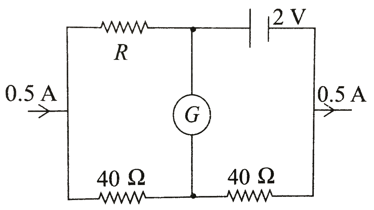
View SolutionIn the circuit shows in Fig. 6.74, the internal resistance of the cell is negligible. For the value of R=40/xΩ, no current flows through the galvanometer. What is x?
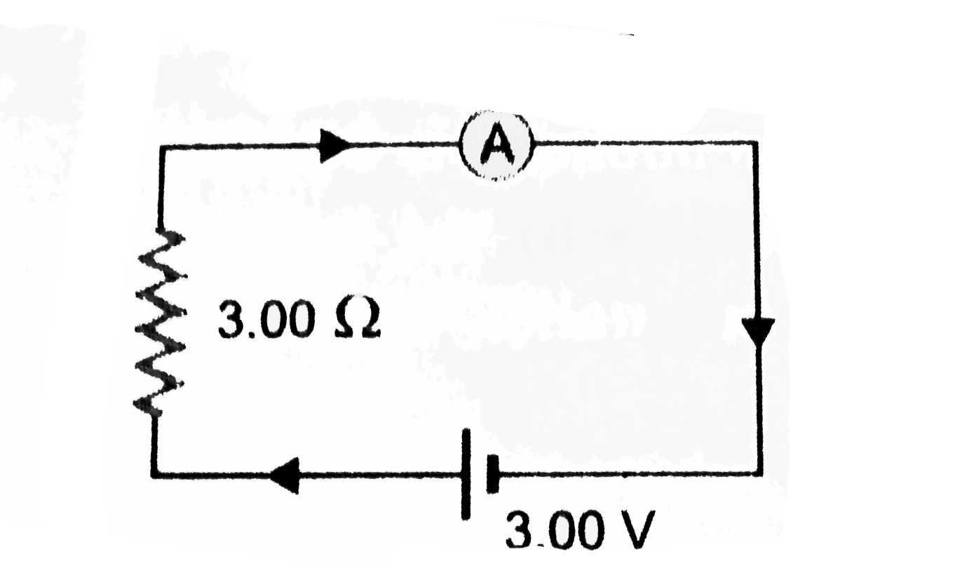
View SolutionIn the circuit shown in figure, the current is to measured. What is the value of the current if the ammeter shown (i) is a galvanometer with a resistance RG=60⋅00Ω. (ii) is a galvanometer described in (i) but converted to an ammeter by a shunt resistance rs=0⋅02Ω, (iii) is an ideal ammeter with zero resistance?
View SolutionIn the circuit shown below, E is a battery of emf 6 V and internal resistance 1Ω. Find the reading of the ammeter A. if it has negligible resistance :

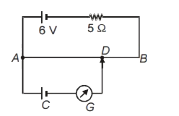
View SolutionIn the potentiometer circuit shown in the figure the internal resistance of the 6V battery is 1Ω and length of the wire AB is 100 cm . When AD = 60 cm , the galvanometer shows no deflection . The EMF of the cell C is (the resistance of the wire AB is 2Ω )
View Solution
