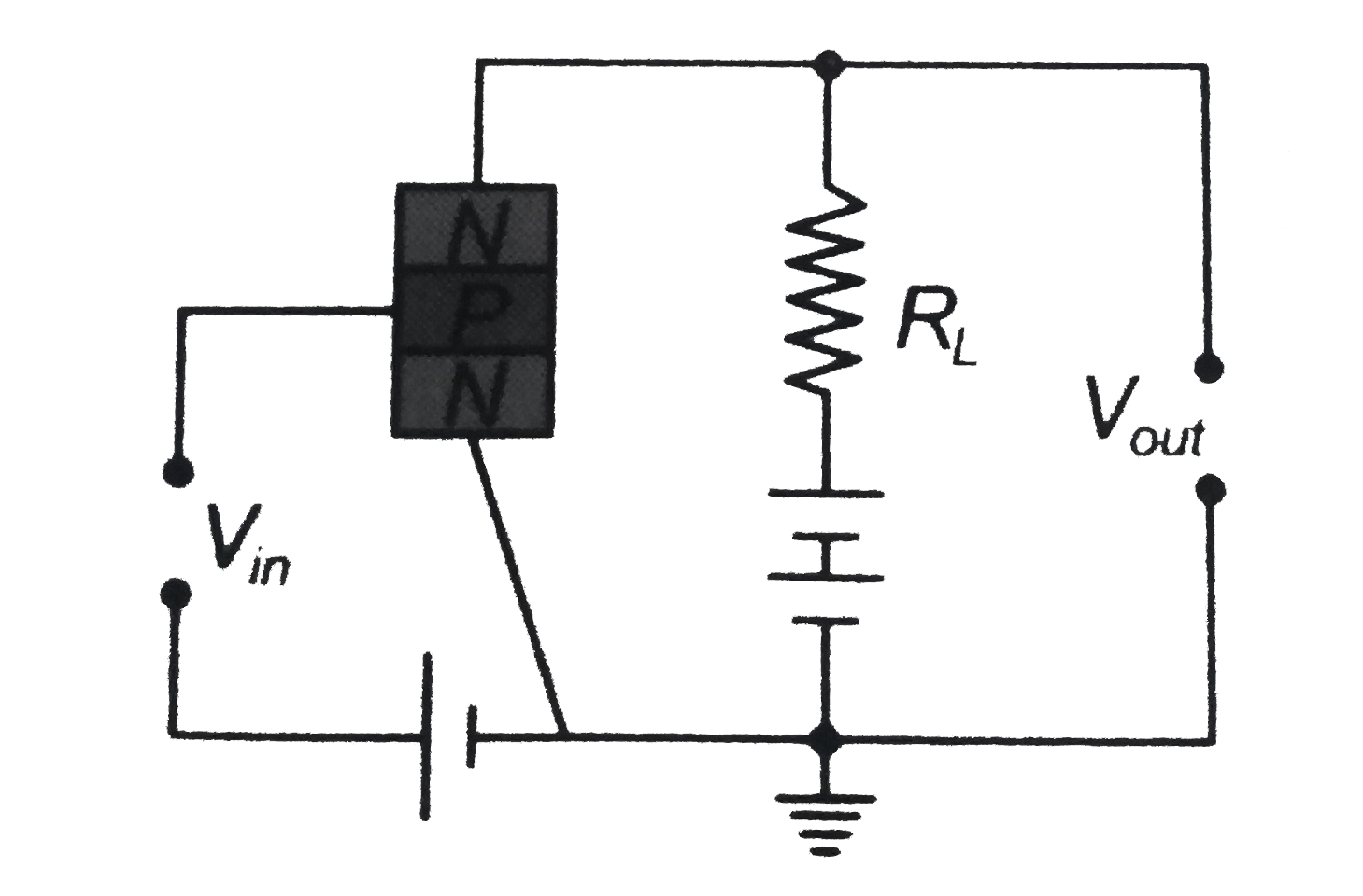
Consider the transistor shown in figure, its terminals are marked as 1,2 and 3. Using multimeter one try to identify the base of transistor, he proceed in the way as follows. Experiment I: He touches the common lead of the multimeter to 2, then on touching other lead of multimeter to 1 he hasn.t got any beep (indication of conduction) but when connected to 3 got the beep.
Experiment II: He connected the common lead of multimeter to 1 and other lead to 2 and 3 one by one then in this case he got beep for both connections. From this we conclude that

1 is base
2 is base
3 is base
none of these
The correct Answer is:B
Step by step video & image solution for Consider the transistor shown in figure, its terminals are marked as 1,2 and 3. Using multimeter one try to identify the base of transistor, he proceed in the way as follows. Experiment I: He touches the common lead of the multimeter to 2, then on touching other lead of multimeter to 1 he hasn.t got any beep (indication of conduction) but when connected to 3 got the beep. Experiment II: He connected the common lead of multimeter to 1 and other lead to 2 and 3 one by one then in this case he got beep for both connections. From this we conclude that by Physics experts to help you in doubts & scoring excellent marks in Class 12 exams.
Topper's Solved these Questions
- BOOK - AAKASH SERIESCHAPTER - PRACTICAL PHYSICSEXERCISE - LECTURE SHEET LEVEL-II (ADVANCED) Linked Comprehension Type Questions4videos
PRACTICAL PHYSICS
- BOOK - AAKASH SERIESCHAPTER - PRACTICAL PHYSICSEXERCISE - LECTURE SHEET LEVEL-II (ADVANCED) Linked Comprehension Type Questions4videos
PRACTICAL PHYSICS
- BOOK - AAKASH SERIESCHAPTER - PHYSICAL WORLDEXERCISE - Exercise -I10videos
PHYSICAL WORLD
- BOOK - AAKASH SERIESCHAPTER - RAY OPTICSEXERCISE - PROBLEMS ( LEVEL-II)60videos
RAY OPTICS
Similar Questions
Knowledge Check
- Question 1 - Select One
A transistor connected in common emitter mode, the voltage drop across the collector is 2 V and β is 50, the base current if RC is 2kΩ is
A40μAB20μAC30μAD15μA
An NPN-transistor circuit is arranged as shown in figure. It is
 View Solution
To identify whether the transistor is working or not, using multimeter, which statement serves the purpose?
View SolutionHugo de Vries formulated the "Mutation Theory" based on the experiments he conducted on
View SolutionA working transistor with its three legs marked P,QandR is tested using a multimeter No conduction is found between P,Q by connecting the common (negative) terminal of the multimeter to R and the other (positive) terminal to P or Q some resistance is seen on the multimeter . Which of the following is true for the transistor ?
View SolutionA working transitor with its three legs marked P,QandR is tested using a multimeter No conduction is found between P,Qby connecting the common (negative) terminal of the multimeter to Rand the other (positive) terminal to or Q some resistance is seen on the multimeter . Which of the following is true for the transistor ?
View SolutionThe diagram in Fig. shows a three-pin socket marked as 1, 2 and 3.

To which part of the appliance is the terminal 1 connected ?View SolutionA working transitor with its three legs marked P,QandR is tested using a multimeter No conduction is found between 'P',Qby connecting the common (negative) terminal of the multimeter to Rand the other (positive) terminal to P or Q some resistance is seen on the multimeter . Which of the following is true for the transistor ?
View Solution

