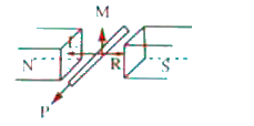
Find the emf induced across the ends of the conductor shown in the figure

e=BVl=BV(l1sinθ1+l2sinθ2)
Topper's Solved these Questions
- BOOK - AAKASH SERIESCHAPTER - ELECTROMAGNETIC INDUCTIONEXERCISE - Exercise (Long Answer Questions)1videos
ELECTROMAGNETIC INDUCTION
- BOOK - AAKASH SERIESCHAPTER - ELECTROMAGNETIC INDUCTIONEXERCISE - Exercise (Short Answer Questions)21videos
ELECTROMAGNETIC INDUCTION
- BOOK - AAKASH SERIESCHAPTER - ELECTROMAGNETIC INDUCTIONEXERCISE - PRACTICE EXERCISE (SELF INDUCTANCE AND MUTUAL INDUCTANCE)12videos
ELECTROMAGNETIC INDUCTION
- BOOK - AAKASH SERIESCHAPTER - ELECTRIC FIELD AND POTENTIALEXERCISE - PROBLEMS (LEVEL-II)26videos
ELECTRIC FIELD AND POTENTIAL
- BOOK - AAKASH SERIESCHAPTER - ELECTROMAGNETIC WAVESEXERCISE - EXERCISE -II22videos
ELECTROMAGNETIC WAVES
Similar Questions
An electric potential difference will be induced between the ends of the conductor shown in the figure, if the conductor moves in the direction shown by
 View Solution
An electric potential difference will be induced between the ends of the conductor shown in the diagram when it moves in the direction
 View Solution
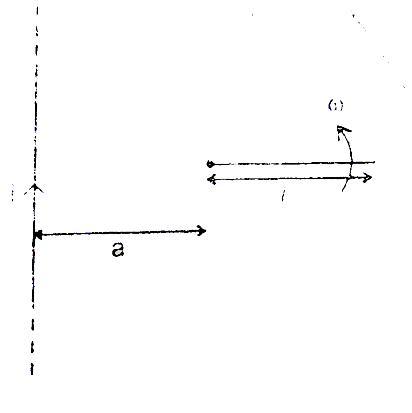
A rod of length l is rotating with an angular speed ω about its one end which is at a distance a from an infinitely long wire carrying current i.Find the emf induced in the rod at the instant shown in the figure.
 View Solution
Find the emfinduced in the rod in the following cases.The figures are self explanatory.
 View Solution
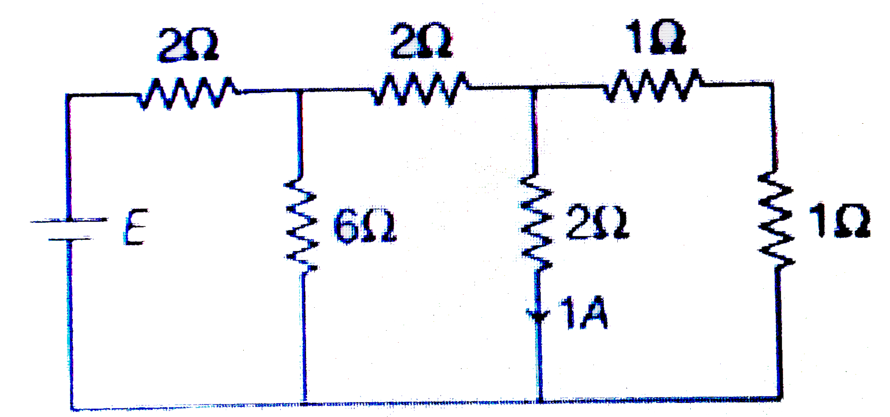
find the emf of the battery shown in figure below:
 View Solution
The emf of the battery shown in figure is
 View Solution
If the potential difference across the ends of a conductor is doubled, the energy loss becomes-
View SolutionFind magnetic field at O due to the current carrying conductor as shown in the figure.
 View Solution
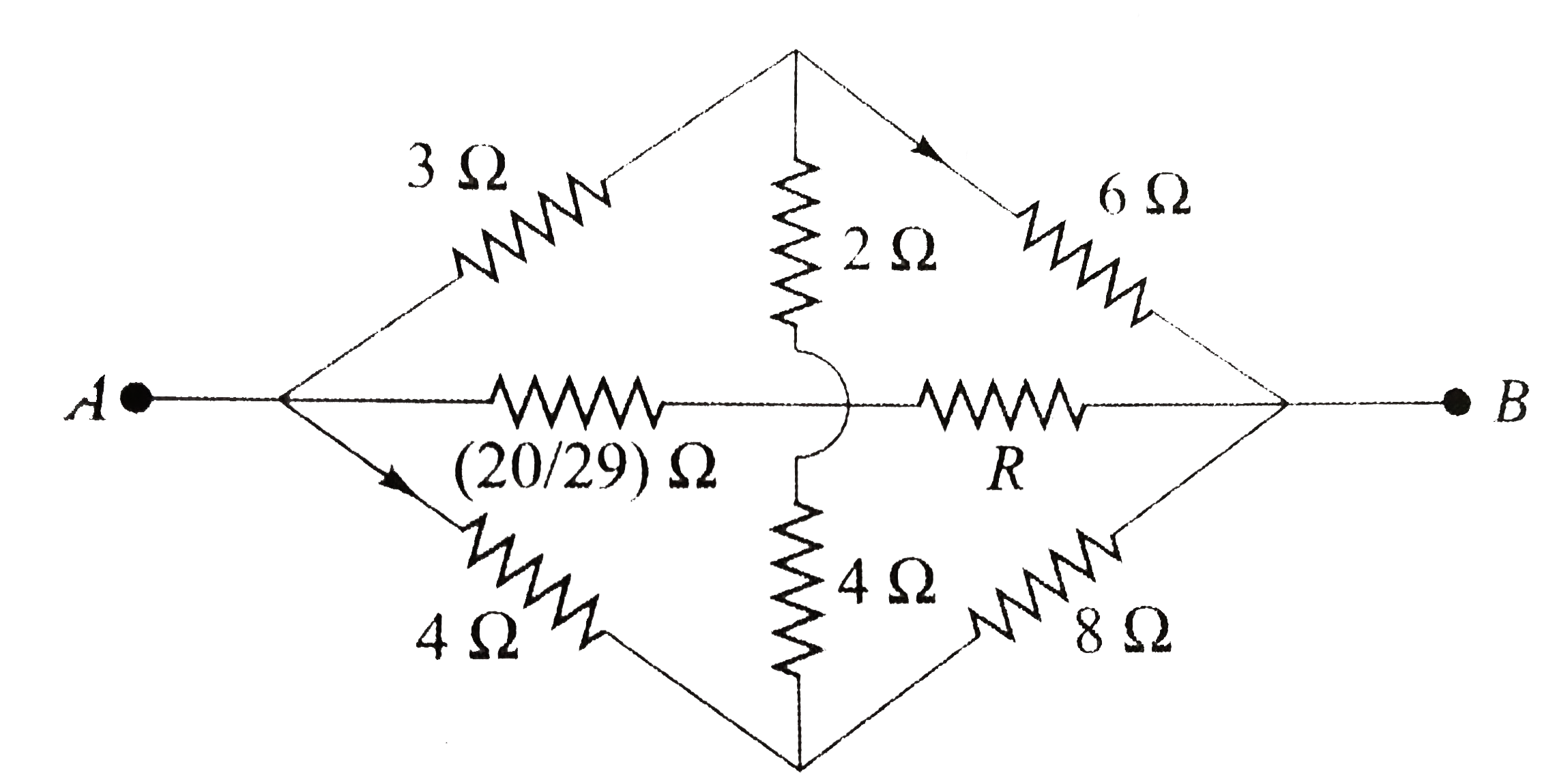
A battery of emf 2 V and initial resistance 1Ω is
connected across terminals A and B of the circuit shown
in figure
 . View Solution
A conductor of 3m in length is moving perpendicularly to magnetic field of 10−4 tesla with the speed of 102m/s, then the e.m.f. produced across the ends of conductor will be
View Solution

