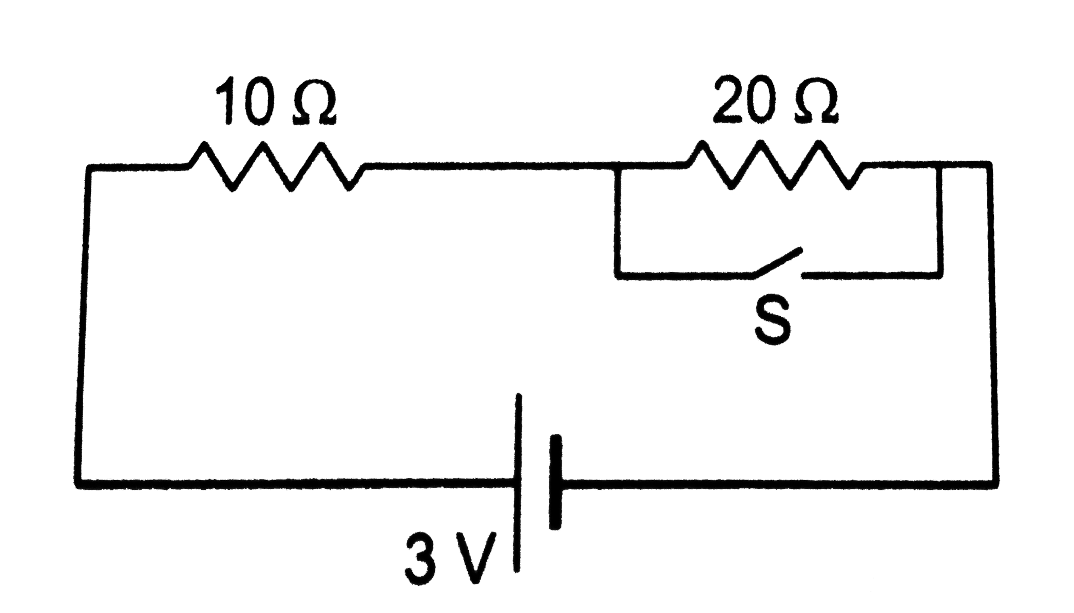
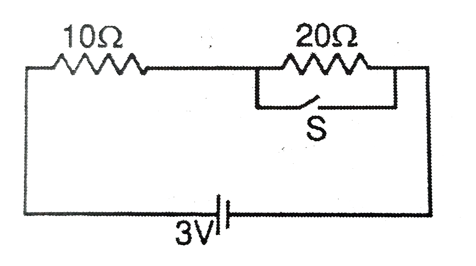
Consider the circuit shown in figure.Find the current through the10(Ω)resistor when the switch S is (a)open (b)closed .
 Solution in Gujrati
(a) When S is open
Req=(10+20)Ω=30Ω
i=(330)A=0.1A
When S is closed
Req=10Ω
i= (3/30) A = 0.3 A.
Topper's Solved these Questions
- ELECTRIC CURRENT IN CONDUCTORSBOOK - HC VERMACHAPTER - ELECTRIC CURRENT IN CONDUCTORSEXERCISE - Objective 2
9 Videos
- DISPERSION AND SPECTRABOOK - HC VERMACHAPTER - DISPERSION AND SPECTRAEXERCISE - Exercises
11 Videos
- ELECTRIC CURRENT THROUGH GASESBOOK - HC VERMACHAPTER - ELECTRIC CURRENT THROUGH GASESEXERCISE - Exercises
23 Videos
Similar Questions
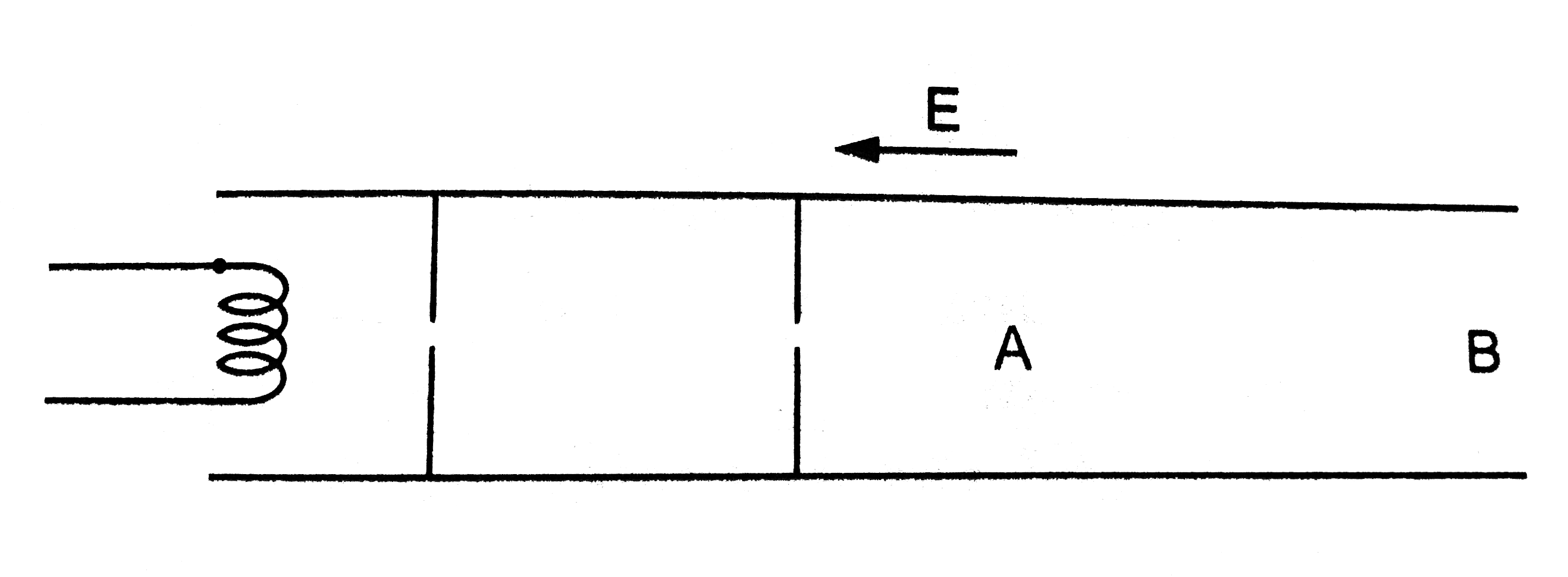
Electrons are emitted by a hot filament and are accelerated by an electric field as shown in figure .The two stops at the left ensure that the electron beam has a uniform cross-section.
View SolutionA flint glass prism and a crown glass prism are to be combined in such a way that the deviation of the mean ray is zero. The refractive index of flint and crown glasses for the mean ray are 1.620 and 1.518 respectively. If the refracting angle of the flint prism is 6.0∘, what would be the refracting angle of the crown prism ?
View SolutionA discharge tube contains helium at a low pressure. A large potential difference is applied across the tube. Consider a helium atom that has just been ionized due to the detachment of an atomic electron. Find the ratio of the distance travelled by the free electron to that by the positive ion in a short time dt after the ionization.
View SolutionConsider the circuit shown in figure.Find the current through the10(Ω)resistor when the switch S is (a)open (b)closed .

View SolutionConsider the circuit shown in figure.Find (a) the current in the circuit, (b) the potential drop across the (5Ω)resistor,(c )the potential drop across the 10(Ω)resistor.(d)Answer the parts (a),(b)and (c )with reference to figure.

View SolutionThe switch S shown in figure is kept closed for a long time and is then opened at t=0.Find the current in the middle 10(Ω)resistor at t=1.0ms.
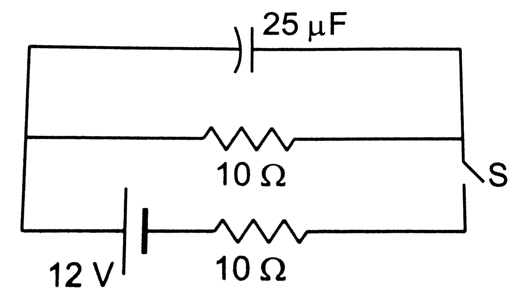
View SolutionIn the circuit arrangement shown in figure, the switch S is closed at t=0. Find the current in the inductance as a function of time? Does the current through 10Ω resistor vary with time or remains constant.
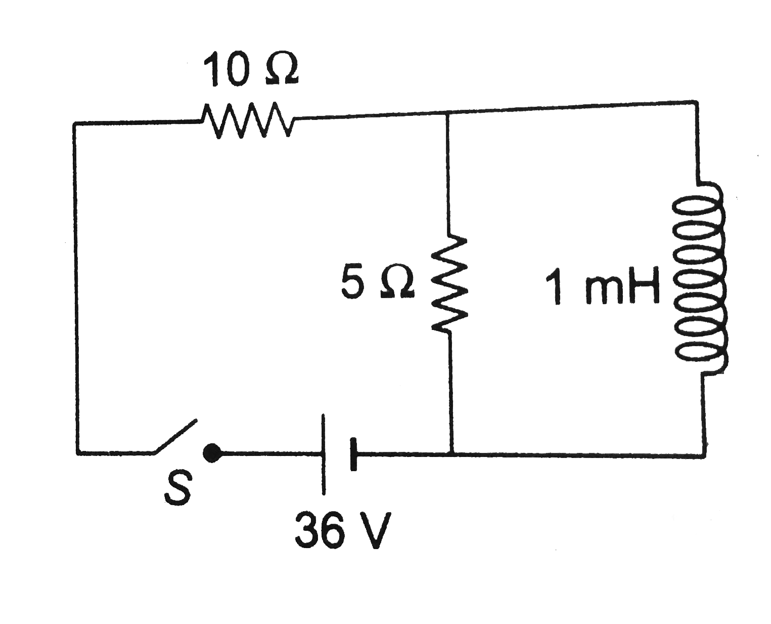
View SolutionThe circuit consists of two resistors (of resistance R1=20Ω and R2=10Ω), a capacitor (of capacitance C=10μF) and two ideal cells. In the circuit shown the capacitor is in steady state and the switch S is open
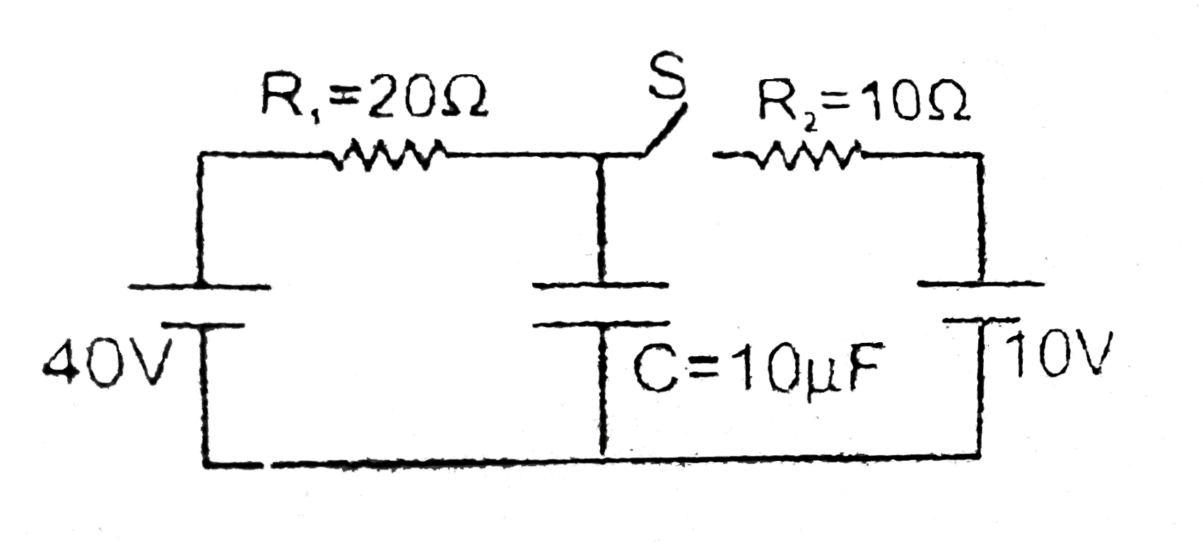
The current through the resistor R2 just after the switch S is closed is :
View SolutionThe circuit consists of two resistors (of resistance R_(1) = 20 Omega and R_(2) = 10 Omega ), a capacitor (of capacitance C =10 muF ) and two ideal cells. In the circuit shown the capacitor is in steady state and the switch S is open the circuit is in steady state with switch S closed. Now the switch S is opened. Just after the switch S is opened. the current through resistance R_(1) is
View SolutionIn the circuit shown in figure, the current through each resistor is I. Find the currents through the resistors immediately after the switch ‘S’ is opened. How much heat will get dissipated in the circuit after thw switch is opened ?
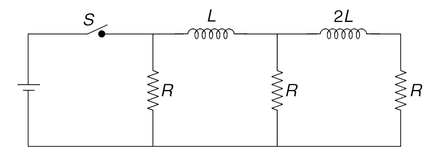
View SolutionIn the circuit shown in figure-3.348 when the switch is closed, the initial current through the 1 Omega resistor just after closing the switch is
View SolutionConsider the circuit shown in figure. Find the current through the 10Ω resistor when the switch S is (a) opened (b) closed.
View SolutionConsider the circuit shown in figure.Find the current through the10(Ω)resistor when the switch S is (a)open (b)closed .

View SolutionConsider the circuit shown in figure.Find (a) the current in the circuit, (b) the potential drop across the (5Ω)resistor,(c )the potential drop across the 10(Ω)resistor.(d)Answer the parts (a),(b)and (c )with reference to figure.

View SolutionThe switch S shown in figure is kept closed for a long time and is then opened at t=0.Find the current in the middle 10(Ω)resistor at t=1.0ms.

View SolutionIn the circuit arrangement shown in figure, the switch S is closed at t = 0 . Find the current in the inductance as a function of time? Does the current through 10 Omega resistor vary with time or remains constant.
View Solution
