The two diods in the figures have negligible resistance when thes are forward biased and are asumed to be ideal. Built in potential in each diode is 0.7V. For the input voltages shown in te figure, the voltage (in volts) at point A is …..
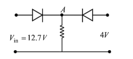
The correct Answer is:12
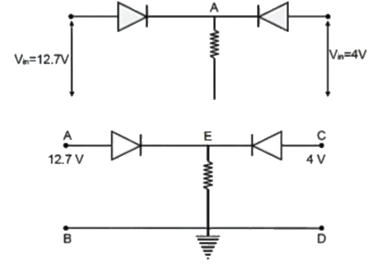
Let VB=0
Right diode is reversed biased and left diode is forward biased
∴VE=12.7−0.7=12volt
Topper's Solved these Questions
Similar Questions
Assuming that the silicon diode (having negligible resistance) the current through the diode is (knee voltage of silicon diode is 0.7V)

View SolutionIn the given circuit both diodes are ideal having zero forward resistance and built-in potential of 0.7 V. Find the potential of point E in volts.

View Solution
Knowledge Check
A full wave rectifier circuit along with the input and output voltages is shown in the figure
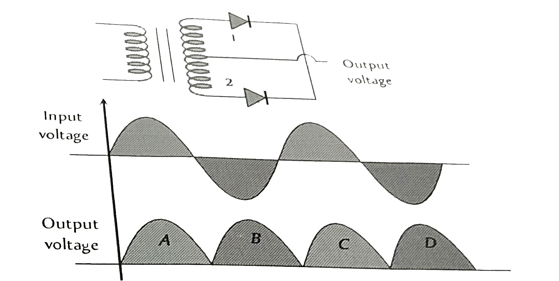
The contribution to output voltage from diode – 2 isAA,CBB,DCB,CDA,DIn the circuit shown in figure, if the A diode forward voltage drop is 0.3 V, the voltage difference between A and B is
 A1.3 VB2.3 VC0D0.5 V
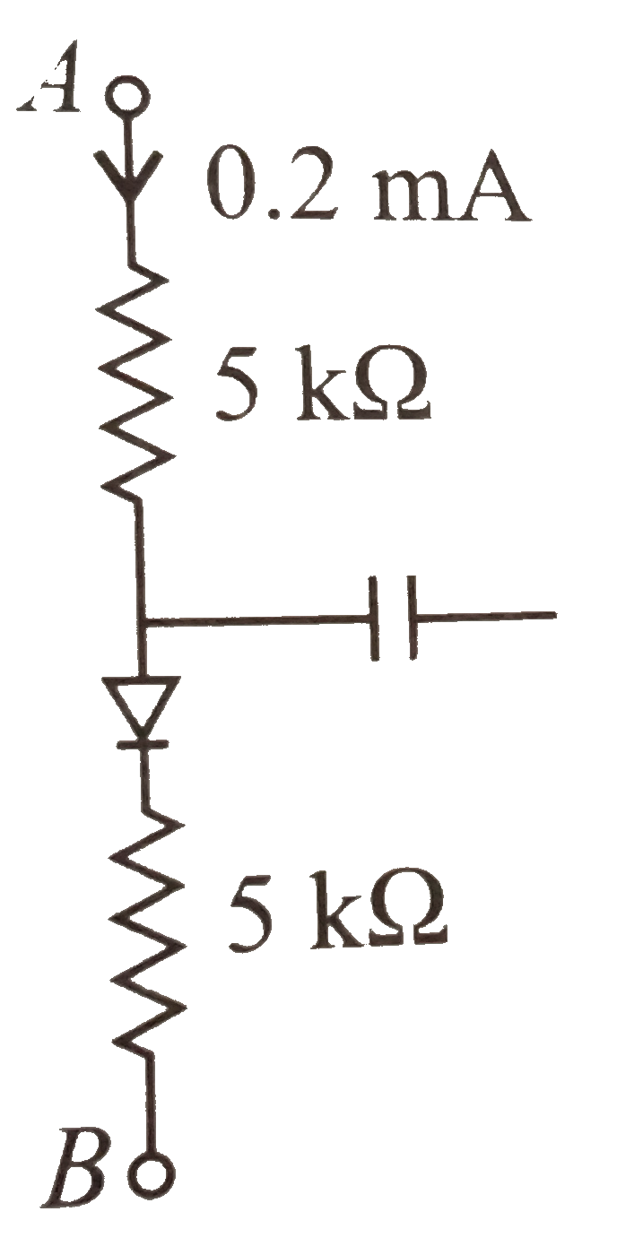
In the circuit shown in figure, if the A diode forward voltage drop is 0.3 V, the voltage difference between A and B is
 A1.3 VB2.3 VC0D0.5 V
In the given circuit both diodes are ideal having zero forward resistance and built-in potential of 0.7 V. Find the potential of point E in volts.

View SolutionTake the breakdown voltage of the zener diode used in the given circuit as 6V. For the input voltage shown in figure below , the time variation of the output voltage is : (Graphs drawn are schematic and not to scale )

View SolutionTake the breakdown voltage of the zener diode used in the given circuit as 6V. For the input voltage shown in figure below , the time variation of the output voltage is : (Graphs drawn are schematic and not to scale )

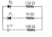
View SolutionThe circuit shown in the figure contains two diodes each with a forward resistance of 50 ohm and with infinite backward resistance. If the battery voltage is 6 V, the current through the 100 ohm resistance (in ampere) is
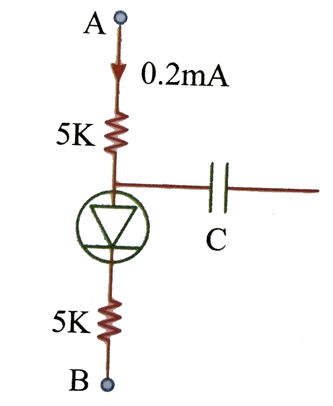
View SolutionIn the circuit shown(Fig.) if the diode forward voltage drop is 0.3V, the voltage difference between A and B is :
 .
.
View Solution
