Case Study :
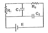
An experiment was set up with the circuit diagram shown in figure.
Given that R1=10Ω,R2=R3=5Ω,r=0Ω and E=5V

The points with the same potential are -
b,c,d
f,h,j
d,e,f
a,b,j
Step by step video & image solution for Case Study : An experiment was set up with the circuit diagram shown in figure. Given that R_1 = 10 Omega,R_2 = R_3= 5 Omega, r = 0 Omega " and " E=5V The points with the same potential are - by Physics experts to help you in doubts & scoring excellent marks in Class 12 exams.
Updated on:21/07/2023Topper's Solved these Questions
- QUESTION PAPER 2022 TERM 1 SET 1BOOK - XII BOARDS PREVIOUS YEARCHAPTER - QUESTION PAPER 2022 TERM 1 SET 1EXERCISE - SECTION-B
24 Videos
- QUESTION PAPER 2022 SET - 5BOOK - XII BOARDS PREVIOUS YEARCHAPTER - QUESTION PAPER 2022 SET - 5EXERCISE - SECTION-C (CASE STUDY)
5 Videos
- QUESTION PAPER 2022 TERM 1 SET 2BOOK - XII BOARDS PREVIOUS YEARCHAPTER - QUESTION PAPER 2022 TERM 1 SET 2EXERCISE - SECTION C
6 Videos
Similar Questions
Knowledge Check
In the circuit shown in figure
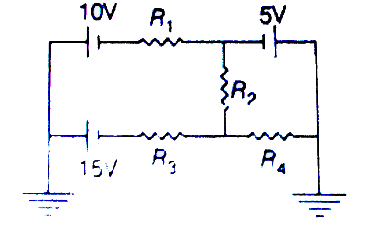
Current through R2 is zero if R4=2Ω and R3=4Ω In this caseACurrent through R3 is 2ABCurrent through R4 is 3ACboth (a) and (b) are correctDboth (a) and (b) wrongConsider the circuit shown in fig.
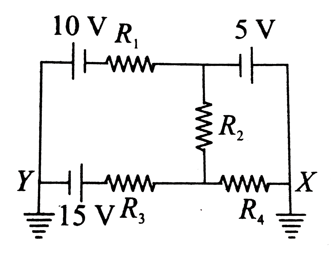
Current through R2 is zero if R4=2ΩandR3=4Ω in this caseACurrent through R3=2.5ABCurrent through R4=3ACboth (a) and (b) are correctDboth (a) and (b) are wrongIn the circuit shown below E1=4.0V,R1=2Ω,E2=6.0V,R2=4Ω and R3=2Ω. The current I1 is
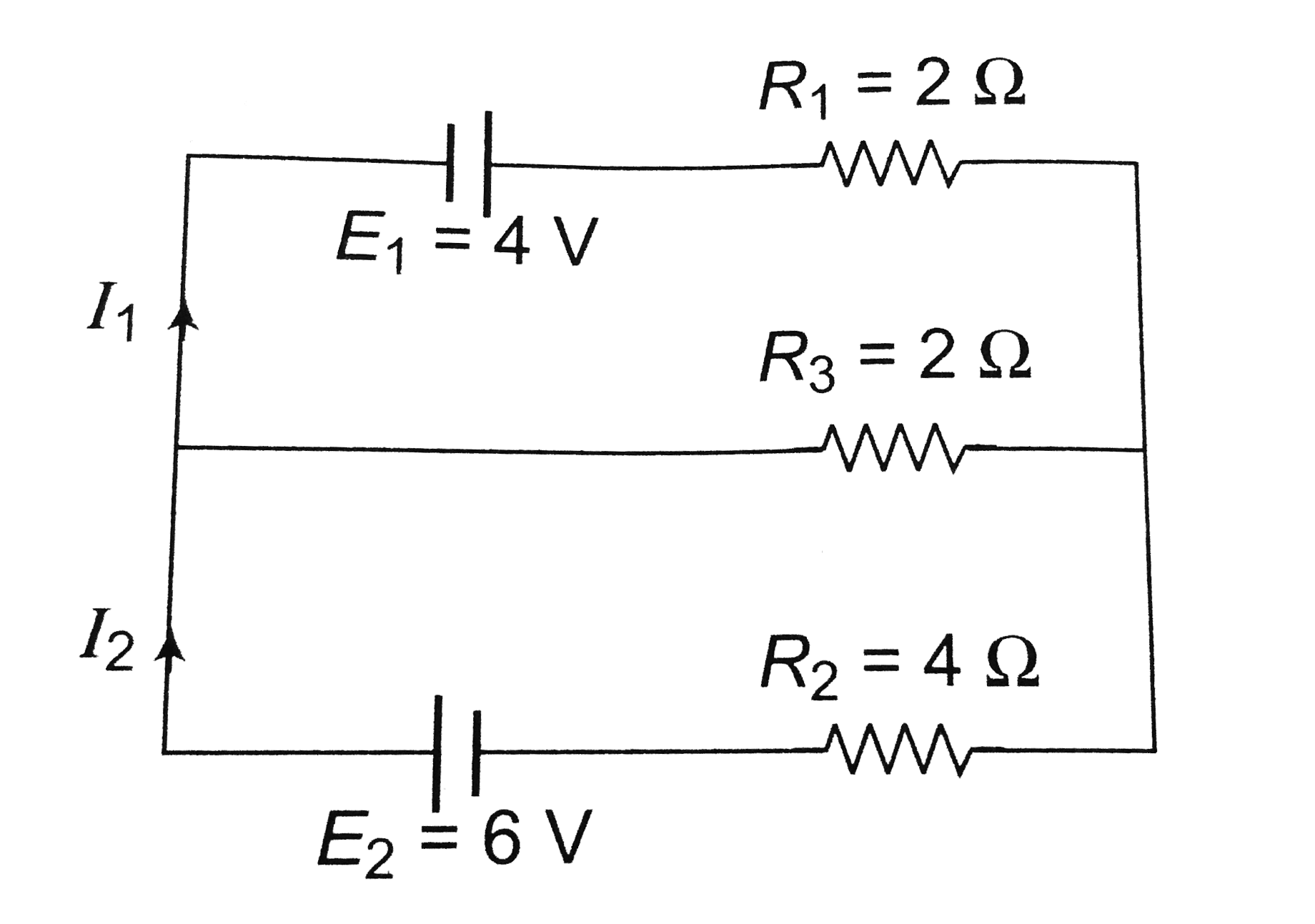 A1.6AB1.8AC1.25AD1.0A
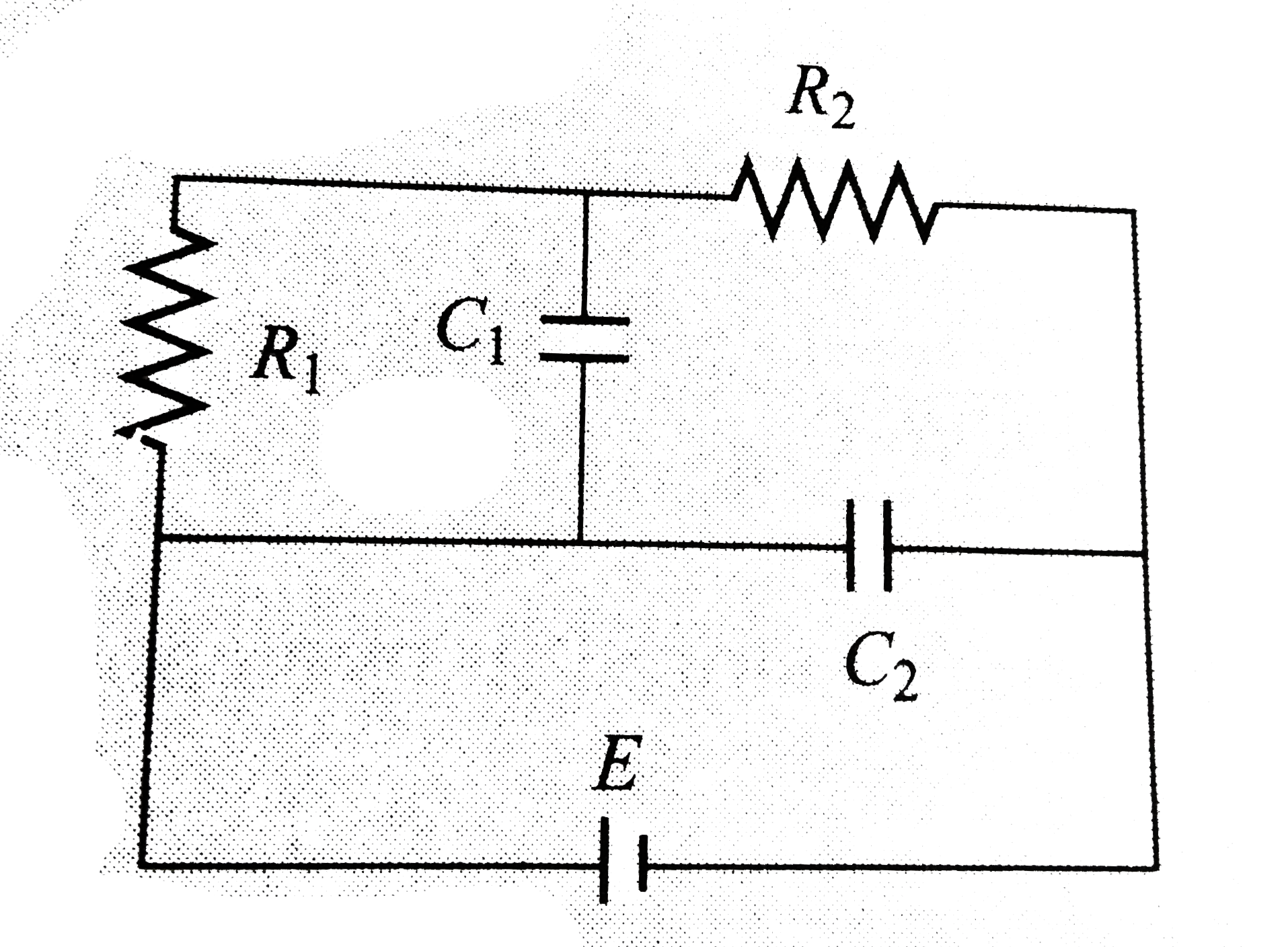
In the circuit shown in fig. R1=10Ω,R2=Ω,C1=1μF,C2=2μF, and E =6V. Calculate the charge on each capactor in the stedy state.
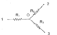
View SolutionFind the current flowing through the resistance R1 of the circuit shown in figure if the resistances are equal to R1=10Ω,R2=20ΩandR3,=30Ω and the potentials of the points 1, 2, and 3 are equal to φ1=10V,φ2=6Vandφ3=5V
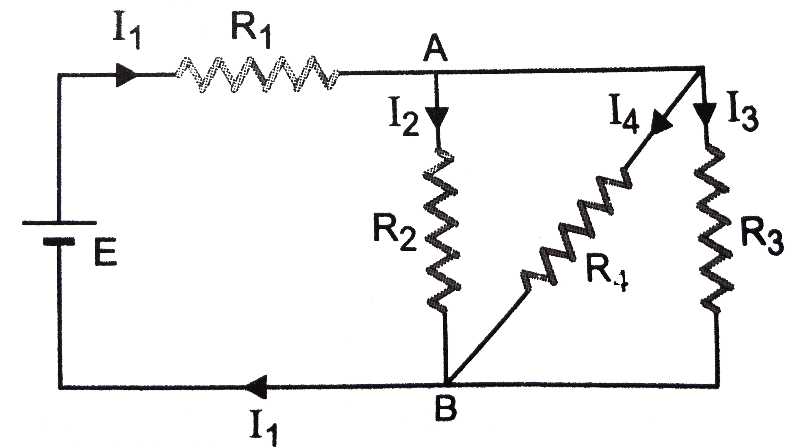
View SolutionIn the circuit R1=4Ω,R2=R3=15ΩR4=30ΩandE=10V Calculate the equivalent resistance of the circuit and current in each resistor
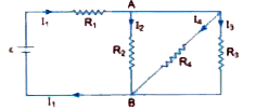
View SolutionIn the circuit shown , R1=4Ω,R2=R3=15Ω,R4=30Ω and ε=10V . Calculate the equivalent resistance of the circuit and the current in each resistor.
View SolutionIn the circuit shown in figure, R(1)=1Ω,R2=2Ω,C1=1μF,C2=2μF and E=6V. Calculate charge on each capacitor in steady state
View Solution

