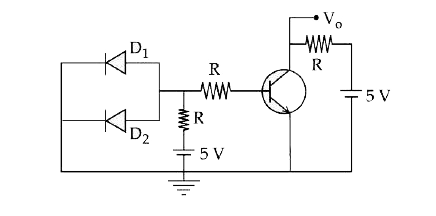
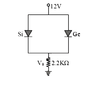
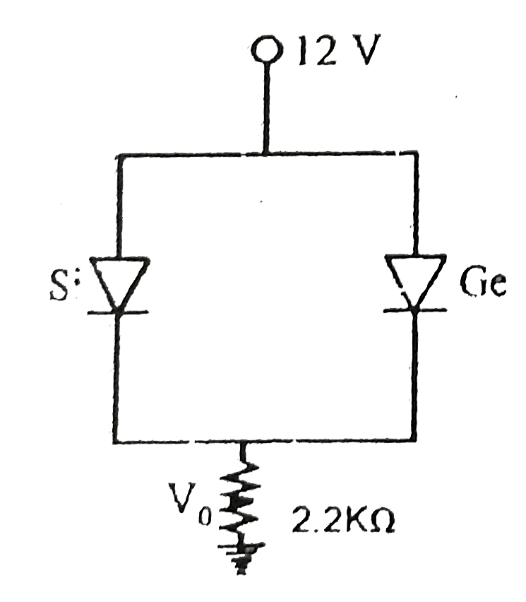
In the circuit shown in figure the maximum output voltage V0 is
A
0V
B
5 V
C
10 V
D
5√2V
Video Solution
Text Solution
The correct Answer is:B

For+ve half,D1→OFF,D2→ON
(V0)max=12×(Vi)max=5V
|
Topper's Solved these Questions
- ELECTRONICSBOOK - ERRORLESSCHAPTER - ELECTRONICSEXERCISE - NCERT Based Questions (Junction Transistor)
29 Videos
- ELECTRONICSBOOK - ERRORLESSCHAPTER - ELECTRONICSEXERCISE - NCERT Based Questions (Digital Electronics)
23 Videos
- ELECTRONICSBOOK - ERRORLESSCHAPTER - ELECTRONICSEXERCISE - Assertion & Reason
26 Videos
- ELECTRON, PHOTON, PHOTOELECTRIC EFFECT & X -RAYBOOK - ERRORLESSCHAPTER - ELECTRON, PHOTON, PHOTOELECTRIC EFFECT & X -RAYEXERCISE - ASSERTION & REASON
27 Videos
- ELECTROSTATICSBOOK - ERRORLESSCHAPTER - ELECTROSTATICSEXERCISE - ASSERTION & REASON
25 Videos
Similar Questions
Knowledge Check
In the circuit shown in the figure, the input voltage Vi is 20V,VBE=0 and VCE=0. The values of IB,IC and β are given by:
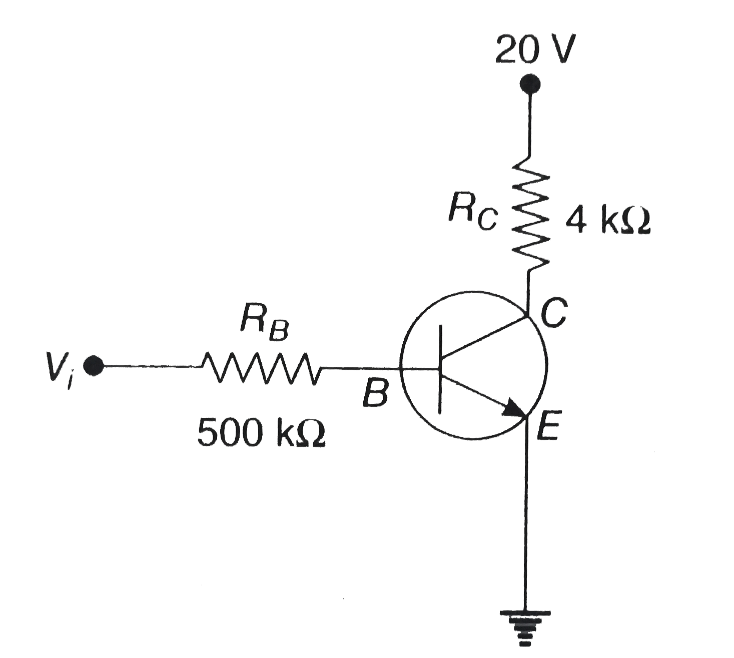 AIB=40μA,IC=10mA,β=250BIB=25μA,IC=5mA,β=200CIB=20μA,IC=5mA,β=250DIB=40μA,IC=5mA,β=125
In the circuit shown in the figure, the input voltage Vi is 20V, VBE=0 and VCE=0. The values of IB, IC and β are given by
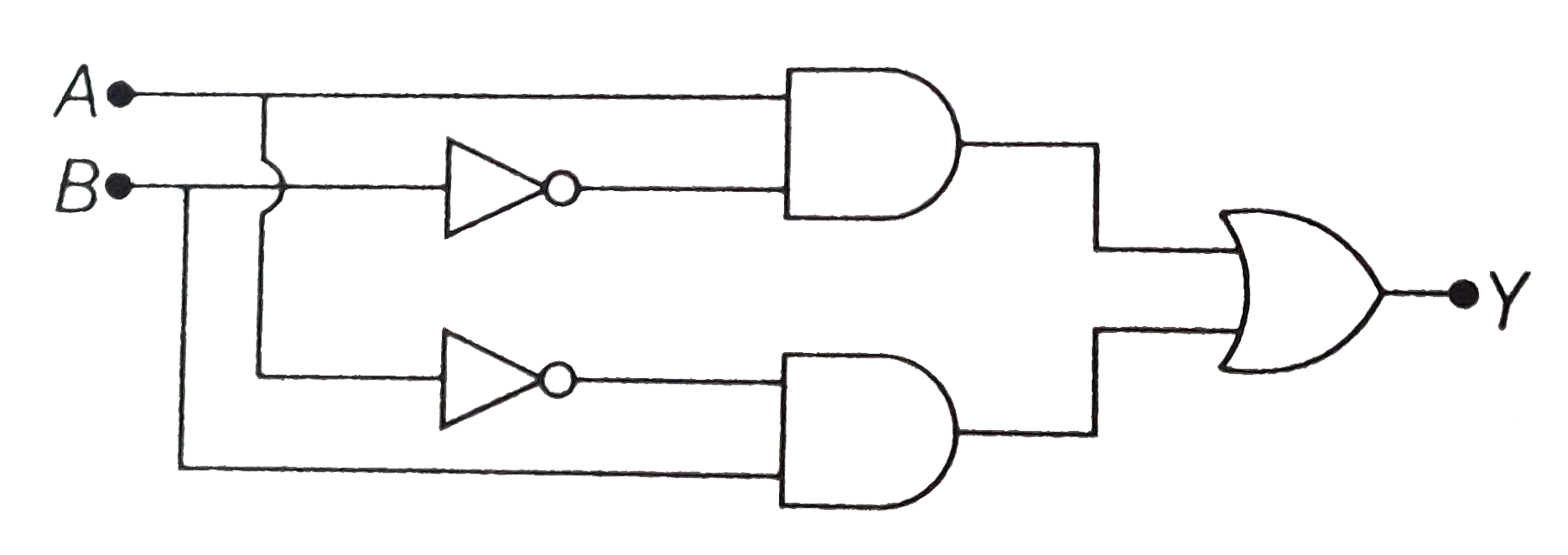 A¯¯¯¯¯¯¯¯A.B+A.BBA.¯¯¯B+¯¯¯A.BC¯¯¯¯¯¯¯¯A.BD¯¯¯¯¯¯¯¯¯¯¯A+B
In the circuit shown in figure , V must be
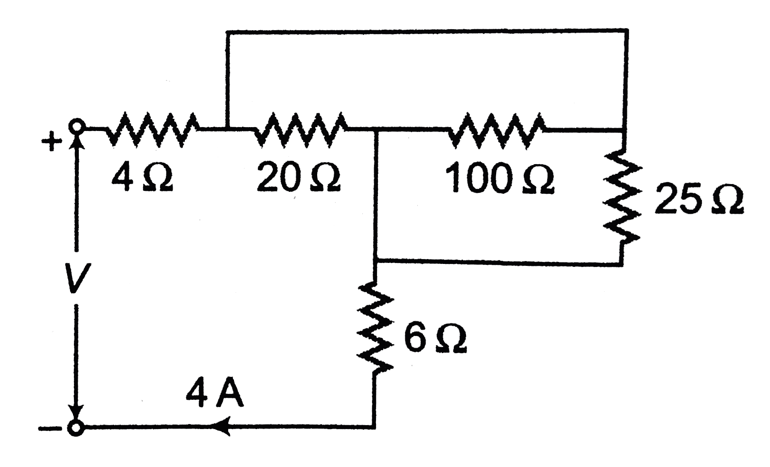 A50VB80VC100VD1290V
In the circuit shown in figure, Voltage V0 is–
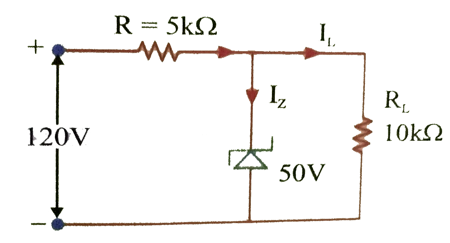
View SolutionFor the circuit shown in figure, Find
(1) the output voltage ,
(2) the voltage drop across series resistance ,
(3) the current through Zener diode.
 .
.
View SolutionIn the circuit shown in the figure, the input voltage Vi is 20V,VBE=0 and VCE=0. The values of IB,IC and β are given by:

View SolutionIn the circuit shown in the figure, the input voltage Vi is 20V,VBE=0 and VCE=0. The values of IB,IC and β are given by:

View SolutionIn the circuit shown in figure, Voltage V0 is
View Solution

