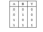
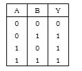
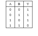
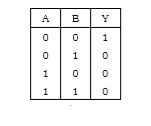
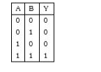
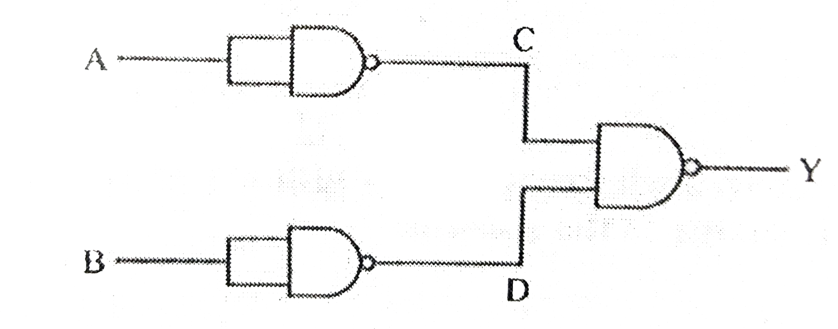
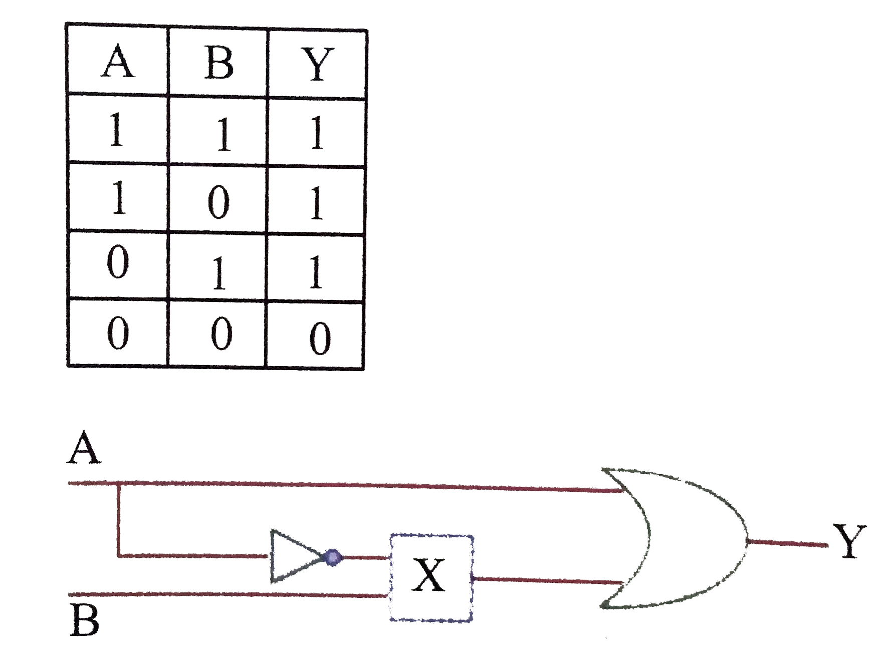
For the logic circuit shown, the truth table is

A
B
C
D
Video Solution
Text Solution
The correct Answer is:A

Y=¯¯¯¯¯¯¯¯¯¯¯¯¯¯¯A+¯¯¯B=¯¯¯¯¯¯¯A.¯¯¯¯¯¯B=A.B=AND gate
Truth Table
|
Updated on:21/07/2023
Topper's Solved these Questions
- BOOK - ERRORLESSCHAPTER - ELECTRONICSEXERCISE - Assertion & Reason26videos
ELECTRONICS
- BOOK - ERRORLESSCHAPTER - ELECTRONICSEXERCISE - NCERT Based Questions (Digital Electronics)23videos
ELECTRONICS
- BOOK - ERRORLESSCHAPTER - ELECTRON, PHOTON, PHOTOELECTRIC EFFECT & X -RAYEXERCISE - ASSERTION & REASON27videos
ELECTRON, PHOTON, PHOTOELECTRIC EFFECT & X -RAY
- BOOK - ERRORLESSCHAPTER - ELECTROSTATICSEXERCISE - ASSERTION & REASON25videos
ELECTROSTATICS
Similar Questions
Knowledge Check
- Question 1 - Select One
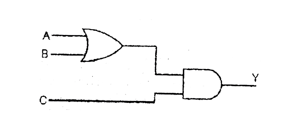
For the logic circuit shown the boolean relation is-AY=ABCBY=A+BCCY=(A+B)CDY=AB+C - Question 2 - Select One or More
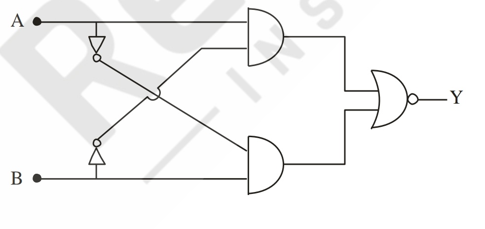
For given logic gate circuit, which truth table is right.
 A
A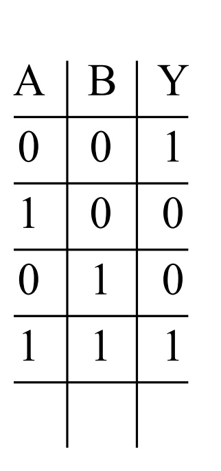 B
B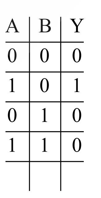 C
C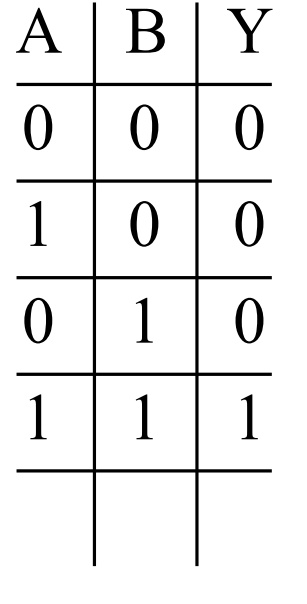 D
D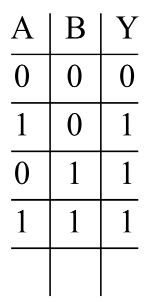
- Question 3 - Select One
The output Y of the logic circuit as shown in figure is
 A(A+B)⋅¯¯¯CB(A+C)⋅¯¯¯CC(B+C)⋅¯¯¯ADA+B+C
Write the truth table for the logic circuit shown below and identify the logic operation performed by circuit.
 View Solution
Identify the logic gates marked P and Q in the given logic circuit. Write down the Boolean expression for this logic circuit and truth table.
 View Solution
The output (X) of the logic circuit shown in figure will be
 View Solution
The output (X) of the logic circuit shown in figure will be
 View Solution
The output (X) of the logic circuit shown in figure will be
 View Solution


 .
.