The capacitor of capacitance C in the circuit shown in fully charged initially. Resistance is R.–
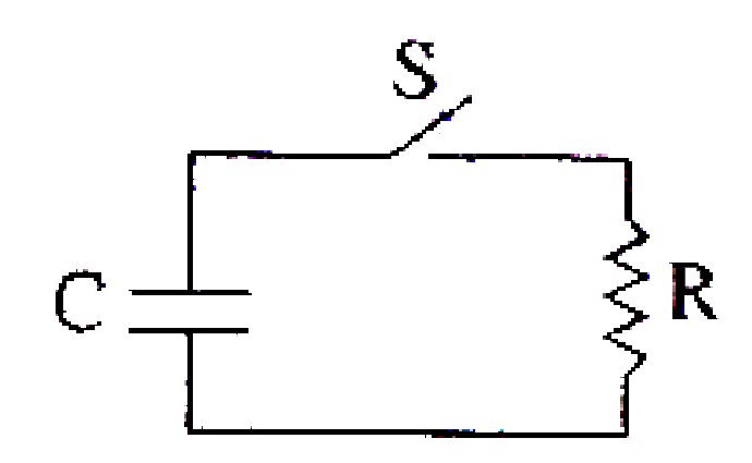
After the switch S is closed, the time taken to reduce the stored energy in the capacitor to half its initial value is
RC2
RCln2
2RCln2
RCln22
The correct Answer is:D
Q=Q0e−t/RC⇒Q0√2=Q0e−t/RC⇒1√2=e−tRC
ln1√2=−tRC⇒tRC=ln√2⇒t=RCln22

Topper's Solved these Questions
- CURRENT ELECTRICITYBOOK - ERRORLESSCHAPTER - CURRENT ELECTRICITYEXERCISE - NCERT BASED QUESTIONS (KIRCHHOFF.S LAW, CELLS)
53 Videos
- CURRENT ELECTRICITYBOOK - ERRORLESSCHAPTER - CURRENT ELECTRICITYEXERCISE - NCERT BASED QUESTIONS (DIFFERENT MEASURING INSTRUMENTS)
74 Videos
- CURRENT ELECTRICITYBOOK - ERRORLESSCHAPTER - CURRENT ELECTRICITYEXERCISE - ASSERTION AND REASON
26 Videos
- ATOMIC AND NUCLEAR PHYSICSBOOK - ERRORLESSCHAPTER - ATOMIC AND NUCLEAR PHYSICSEXERCISE - Assertion and Reason
23 Videos
- ELECTROMAGNETIC INDUCTIONBOOK - ERRORLESSCHAPTER - ELECTROMAGNETIC INDUCTIONEXERCISE - ASSERTION & REASON
20 Videos
Similar Questions
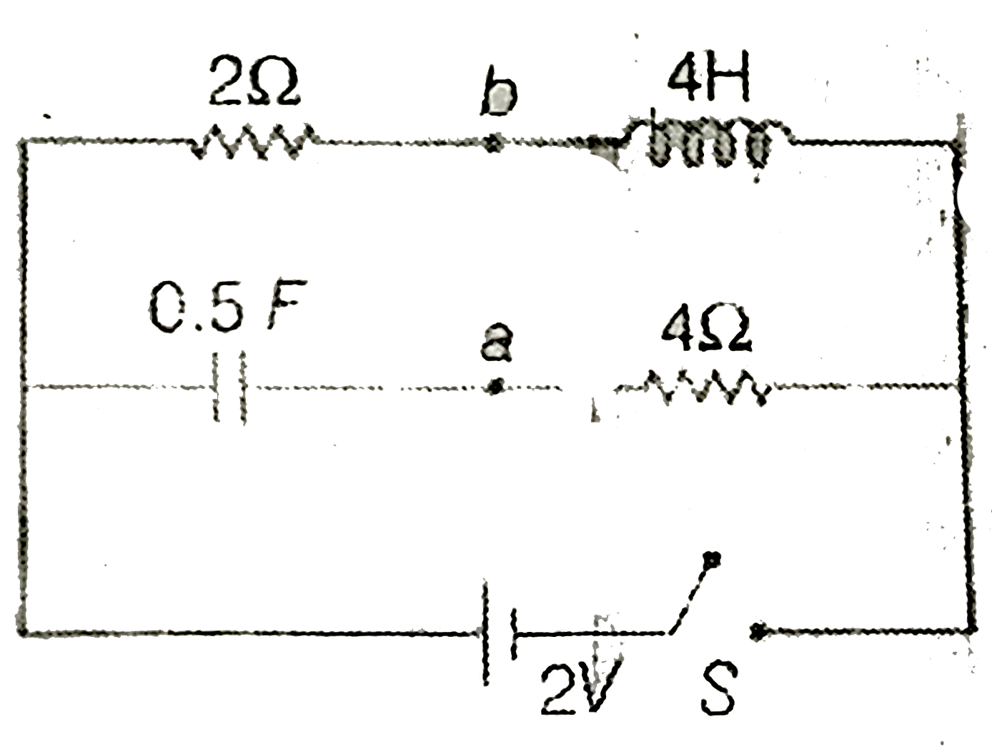
In the circuit shown. Initially the capacitor is uncharged. The switch S is closed at time t=0. Then
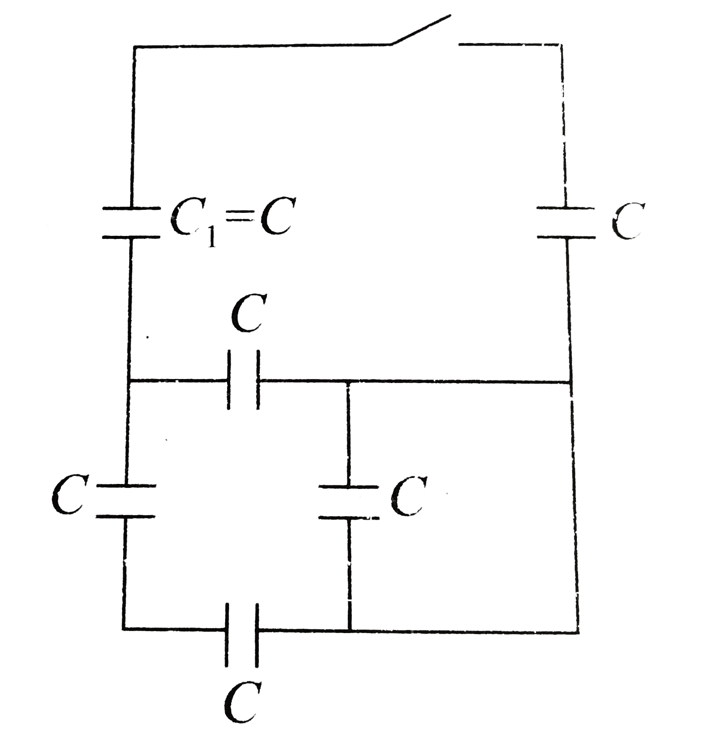
View SolutionIn the circuit shown, all capacitors are identical. Initially, the switch is open and the capacitor marked C1 is the only one charged to a value Q0. After the switch is closed and the equilibrium is reestablished, the charge on the capacitor marked C1 is Q. Find the ratio initial change to final charge in capacitor C1.
View Solution
Knowledge Check
In the circuit shown, the capacitor C1 is initially charged with charge q0. The switch S is closed at time t = 0 . The charge on C2 after time t is
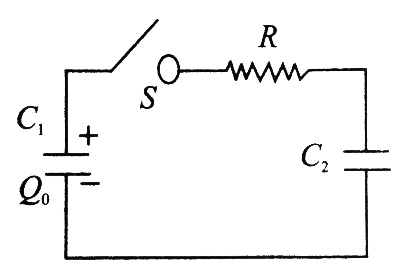 Aq0C1C1+C2(1−e−t(C1+C2)C1C2R)Bq0C2C1+C2(1−e−t(C1+C2)C1C2R)Cq0C1C1+C2(1−e−tC2R)Dq0C2C1+C2(1−e−tC2R)
The two capacitors in the circuit shown in figure are initially uncharged and then connected as shown and switch is closed. What is the potential difference across 3μF capacitor?
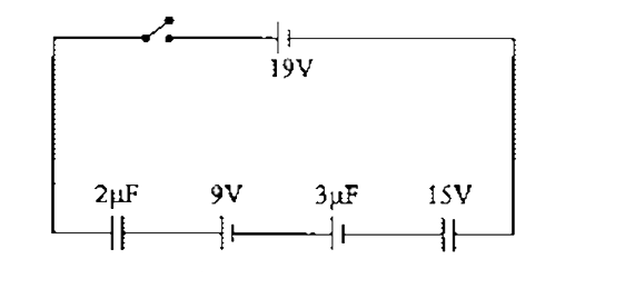 A30VB10VC25VDNone of these
The capacitor shown in the figure is initially unchanged, the battery is ideal. The switch S is closed at time t= 0, then the time after which the energy stored in the capacitor becomes one - fourth of the energy stored in it in steady - state is :
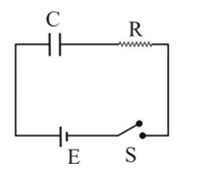 ARCBRC ln 2CRC ln 4D2RC
In the circuit shown in fig. when the switch is closed, the capacitor charges with a time constant
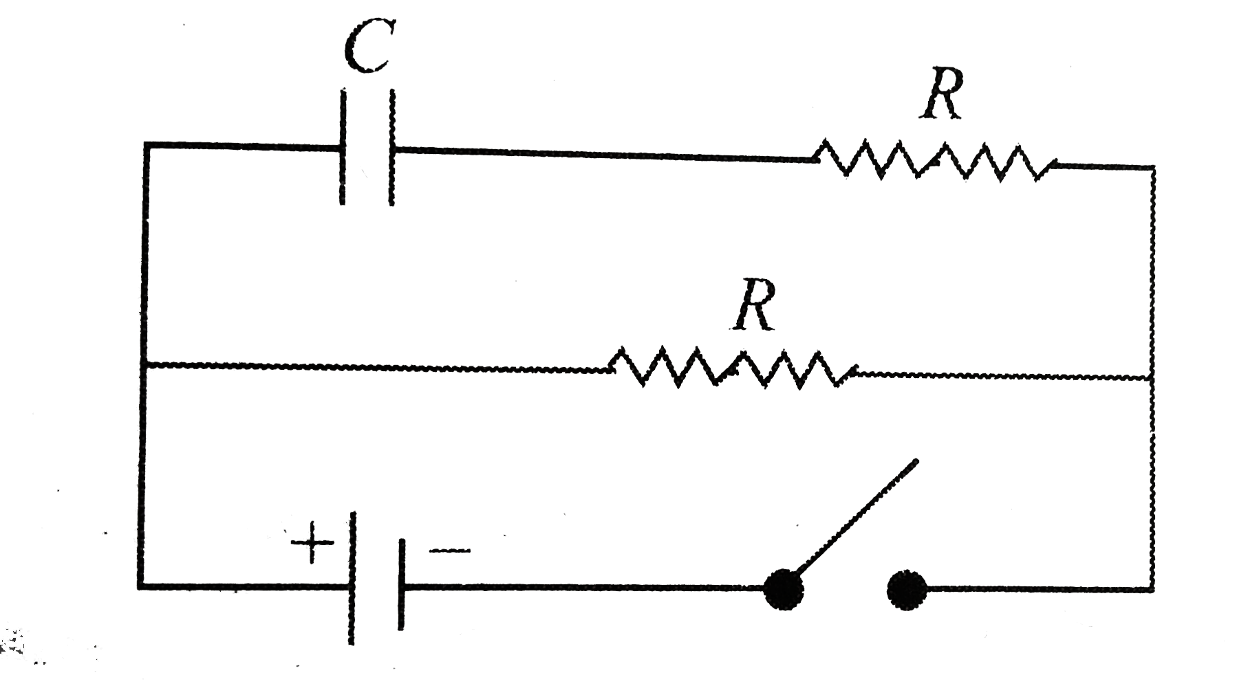
View SolutionIn the circuit shown in fig, if the switch S is closed at t=0 , the capacitor charges with a time constant
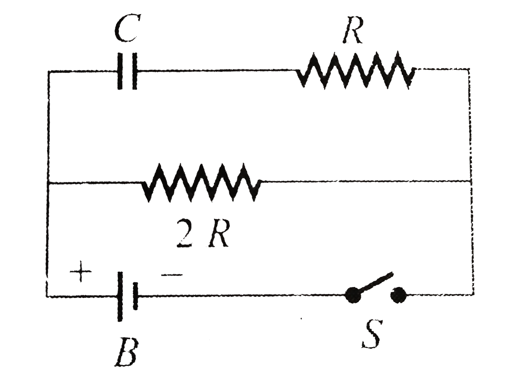
View SolutionThe circuit consists of two resistors (of resistance R1=20Ω and R2=10Ω), a capacitor (of capacitance C=10μF) and two ideal cells. In the circuit shown the capacitor is in steady state and the switch S is open
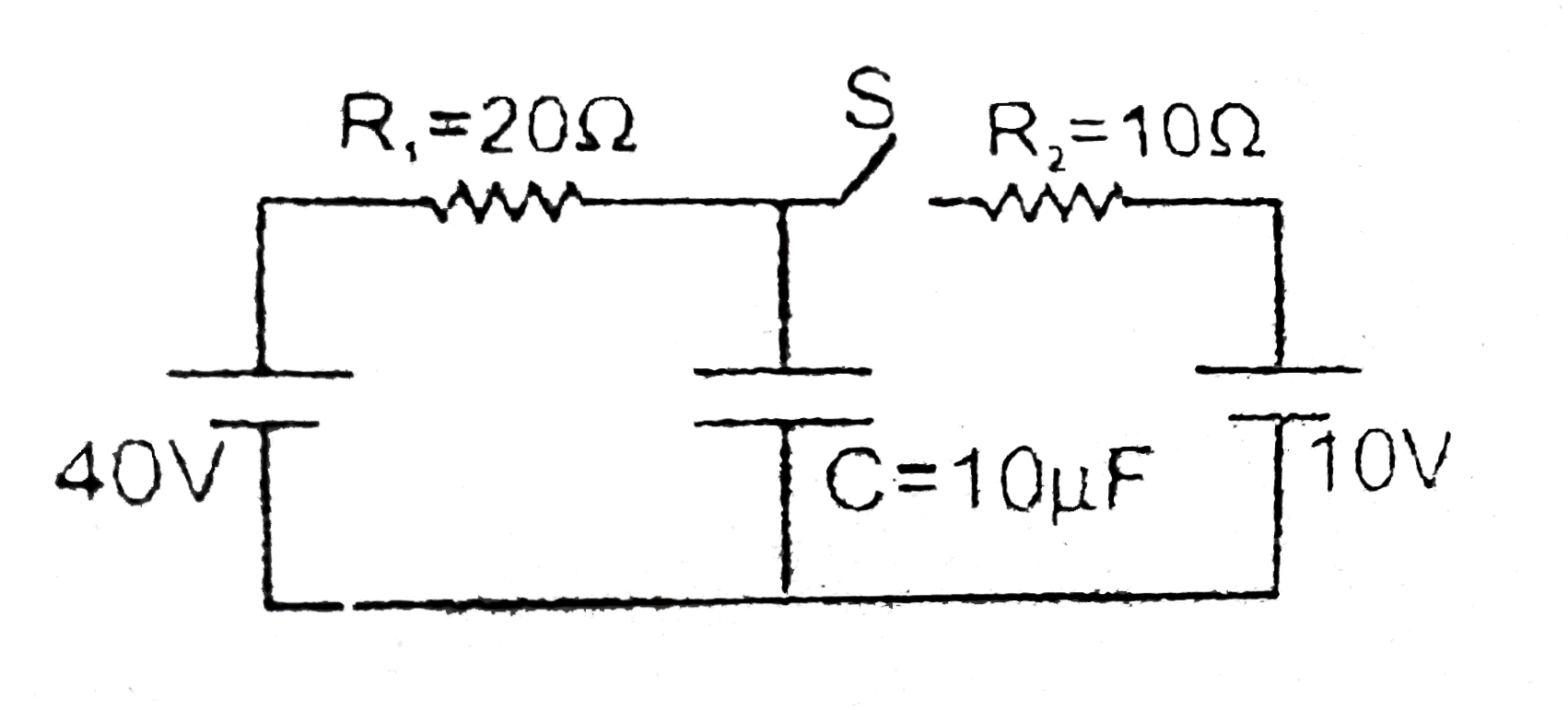
The current through the resistor R2 just after the switch S is closed is :
View SolutionLetC be the capacitance of a capacitor discharging through a resistor R. Suppose t1 is the time taken for the energy stored in the capacitor to reduce to half its initial value and t2 is the time taken for the charge to reduce to one-fourth its initial value. Then the ratio t1/t2 will be
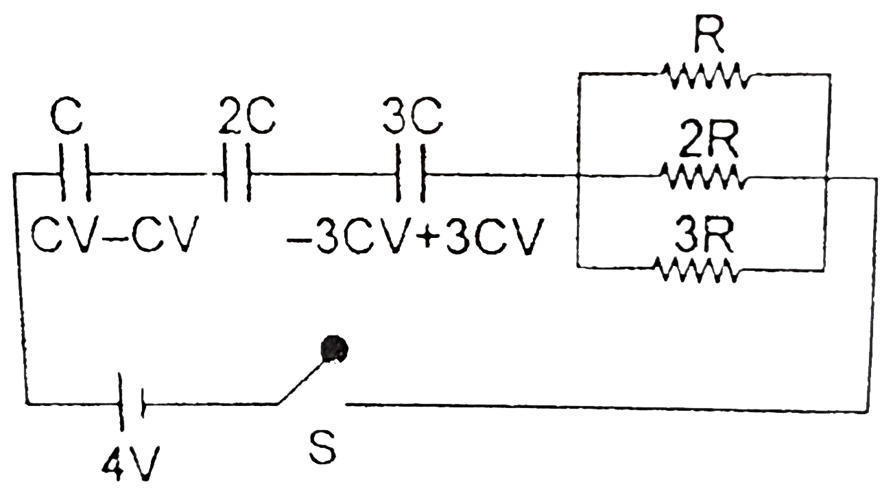
View SolutionThree capacitors (of capacitances C, 2C and 3C) and three resistors (of resistance R, 2R and 3R) are connected with a battery and switch S as shown in the figure. When switch S is open, charges on the capacitors are shown. Switch S is closed at t=0sec. The time constant of the circuit will be
View Solution
