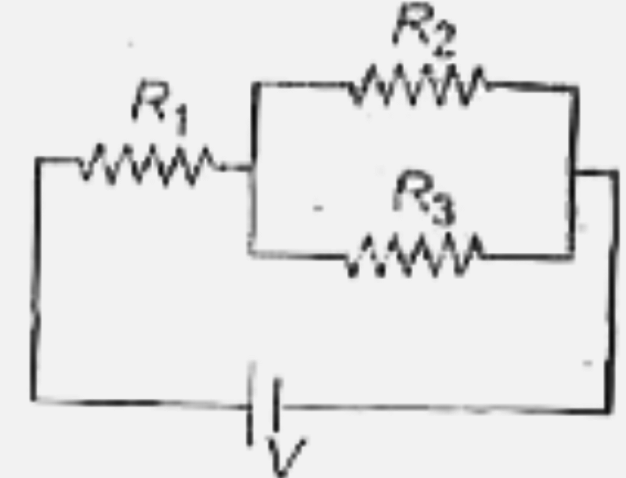
Three resistors R1,R2andR3 are connected in parallel and the combination is connected to a battery, an ammeter, a voltmeter and a key. Draw suitable circuit diagram to show the arrangement of these circuit components along with the direction of current flowing.
To draw the circuit diagram for three resistors R1,R2, and R3 connected in parallel along with a battery, ammeter, voltmeter, and key, follow these steps:
1. Draw the Battery: Start by drawing the battery. Represent the positive terminal with a longer line and the negative terminal with a shorter line.
2. Connect the Key: Draw a switch (key) in series with the battery. This will control the flow of current in the circuit.
3. Draw the Ammeter: Next, draw the ammeter in series with the key. The ammeter is used to measure the current flowing through the circuit. Ensure that the positive terminal of the ammeter is connected to the key.
4. Draw the Resistors in Parallel: From the ammeter, draw three branches going downwards. In each branch, place one resistor \( R_1, R_2, \) and \( R_3 \). Make sure all three branches are connected at the top (to the ammeter) and at the bottom (to a common point).
5. Connect the Voltmeter: Draw the voltmeter across the parallel combination of resistors. The voltmeter should be connected to the same points where the resistors connect at the bottom.
6. Indicate Current Direction: Use arrows to indicate the direction of current flow. The current will flow from the positive terminal of the battery, through the key, into the ammeter, and then split into the three resistors. After passing through the resistors, the current will combine again and return to the negative terminal of the battery.
7. Label the Components: Clearly label the battery, key, ammeter, voltmeter, and resistors \( R_1, R_2, \) and \( R_3 \) in the diagram.
Final Circuit Diagram:
+⊢−|Key⊢−|Ammeter⊢−|R1⊢−|||⊢−|R2⊢−|⊢−|R3⊢−|||⊢−−−−−−−−−−−−−−−−|Vo<meter⊢−−−−−−−|−∣
+⊢−|Key⊢−|Ammeter⊢−|R1⊢−|||⊢−|R2⊢−|⊢−|R3⊢−|||⊢−−−−−−−−−−−−−−−−|Vo<meter⊢−−−−−−−|−∣
Topper's Solved these Questions
- QUESTION PAPER 2022 TERM 2 SET 1BOOK - X BOARDSCHAPTER - QUESTION PAPER 2022 TERM 2 SET 1EXERCISE - SECTION - C
4 Videos
- QUESTION PAPER 2022 TERM 2 SET 1BOOK - X BOARDSCHAPTER - QUESTION PAPER 2022 TERM 2 SET 1EXERCISE - SECTION - C
4 Videos
- QUESTION PAPER 2022 TERM 1 SET 2BOOK - X BOARDSCHAPTER - QUESTION PAPER 2022 TERM 1 SET 2EXERCISE - SECTION C
4 Videos
- QUESTION PAPER 2022 TERM 2 SET 2BOOK - X BOARDSCHAPTER - QUESTION PAPER 2022 TERM 2 SET 2EXERCISE - Section -C
4 Videos
Similar Questions
Three resistors of 5Ω,10Ωand15Ω are connected in series and the combination is connected to battery of 30 V. Ammeter and Voltmeter are connected in the circuit. Draw a circuit diagram to connect all the devices in proper correct order. What is the corrent flowing and potential difference across 10Ω resistance?
View SolutionIf resistors of resistance R1 and R2 are connected in parallel,then resultant resistance is "
View Solution
Knowledge Check
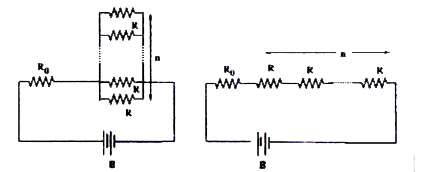
In the circuit shown, n identical resistors R are connected in parallel (n gt 1) and the combination is connected in series to another resistor R0. In the adjoining circuit n resistors of resistance R are all connected in series along with R0–

The batteries in both circuits are identical and net power dissipated in the n resistors in both circuits is same. The ratio R0/R isA1BnCn2D1/nFor three circuits, shown here

the same two resistors R1 and R2 have been connected in parallel in all the circuits but the voltmeter and the ammeter have been connected in three different positions. The relation between the three voltmeter and ammeter readings would be :AV1=V2=V3 and I1=I2=I3BV1≠V2≠V3 and I1=I2=I3CV1=V2=V3 and I1≠I2≠I3DV1≠V2≠V3 and I1≠I2≠I3A cell, a resistor, a key and an ammeter are arranged as known in the circuit diagrams of figure. The current recorded in the ammeter will be
 Amaximum in (i)Bmaximum in (ii)Cmaximum in (iii)Dthe same in all the cases
Three identical resistors R1=R2=R3 are connected as shown to a battery of constant e.m.f . The power dissipated is

View SolutionA resistor is connected to a battery of emf 10 V and internal resistance 0.3Ω. What is the resistance of the resistor to be inserted in the circuit for the circuit current 1.2A?
View SolutionTwo resistances R and 2R are connected in parallel in an electric circuit. The thermal energy developed in R and 2R are in the ratio
View SolutionA ciruit to verify Ohm's law uses ammeter and voltmeter in series or parallel connected correctly to the resistor. In the circuit :
View Solutiontwo resistors R and 2R are connected in series in an electric circuit. The thermal energy developed in R and 2R are in the ratio
View Solution
