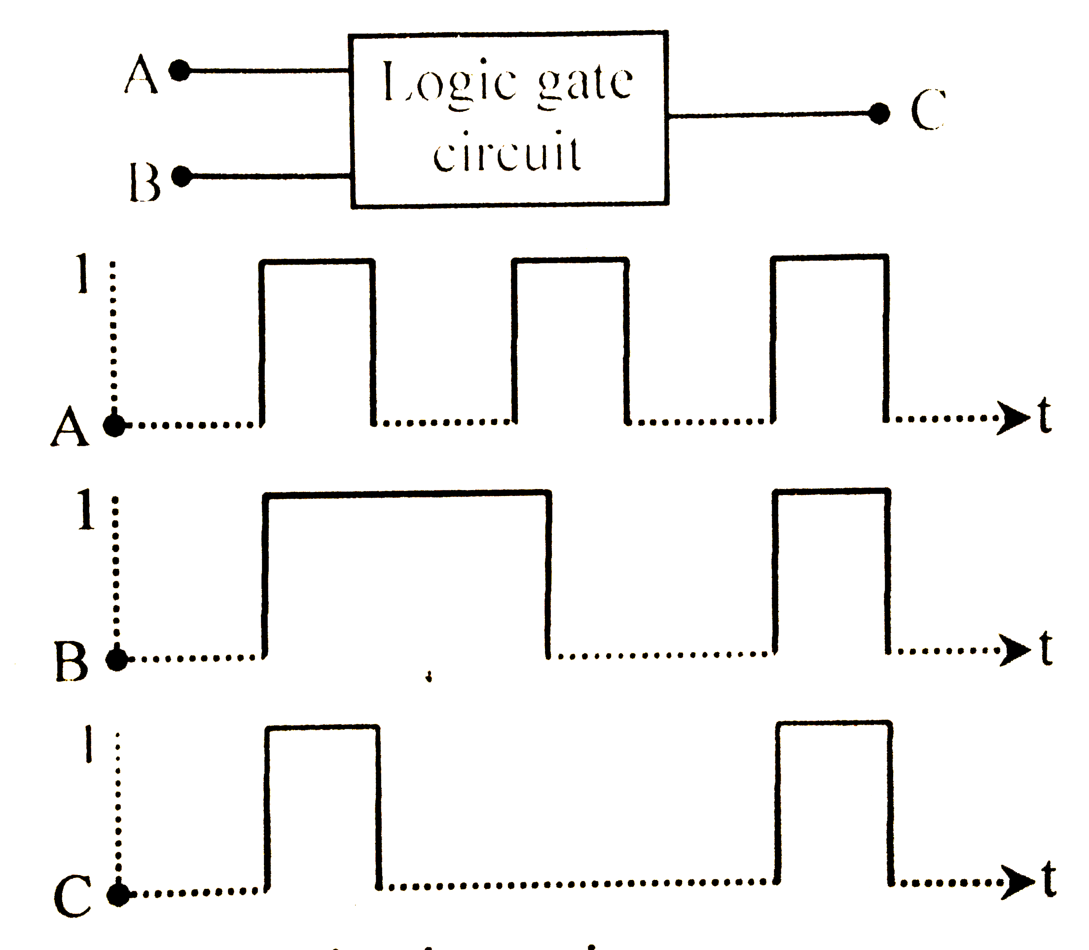
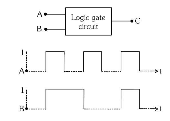
The following figure shows a logic gate circuit with two inputs A and B and the output C. The voltage waveforms of A, B and C are as shown below-
Change in the frequency of light into a change in electric voltage
Change in the intensity of illumination into a change in photoelectric current (
Change in the intensity of illumination into a change in the work function of the photocathode
Change in the frequency of light into a change in the electric current
The correct Answer is:A
In given situation output C is high only when both inputs A and B are high so logic ckt gate is AND gate.
Topper's Solved these Questions
- BOOK - NEET PREVIOUS YEAR (YEARWISE + CHAPTERWISE)CHAPTER - NEETEXERCISE - PHYSICS157videos
NEET
- BOOK - NEET PREVIOUS YEAR (YEARWISE + CHAPTERWISE)CHAPTER - NEETEXERCISE - QUESTION95videos
NEET
- BOOK - NEET PREVIOUS YEAR (YEARWISE + CHAPTERWISE)CHAPTER - MOTION IN TWO AND THREE DIMENSIONEXERCISE - All Questions47videos
MOTION IN TWO AND THREE DIMENSION
- BOOK - NEET PREVIOUS YEAR (YEARWISE + CHAPTERWISE)CHAPTER - NEET 2020EXERCISE - All Questions45videos
NEET 2020
Similar Questions
The following figure shows a logic gate circuit with two inputs A and B and the output C. The voltage waveforms of A, B and C are as given The logic circuit is:
View SolutionThe following figure shows a logic gate circuit with two inputs A and B output C. The voltage waveforms of A,B and C are as shown in second figure given below :-
_E01_436_Q01.png)
The logic circuit gate is :-View Solution
Knowledge Check
- Question 1 - Select One
The following shows a logic gate circuit with two inputs A and B and the output C. The voltage waveforms of A, B and C are as shown below.
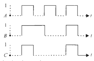
The logic circuit gate isAOR gateBAND gateCNAND gateDNOR gate - Question 2 - Select One
The following figure shows a logic gate circuit with two inputs A and B and the output Y. The voltage waveforms of A,B and the output Y are as given
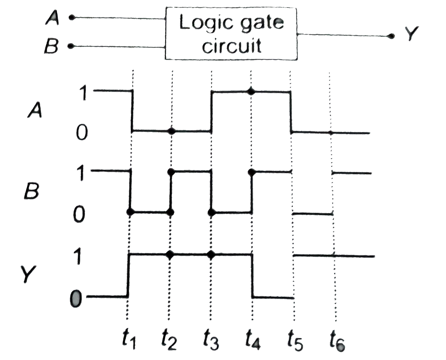 ANOR gateBOR gateCAND gateDNAND gate
 - Question 3 - Select One
The following figure shows a logic gate circuit with two inputs A and B and the output Y. The voltage waveforms of A,B and Y are as given :
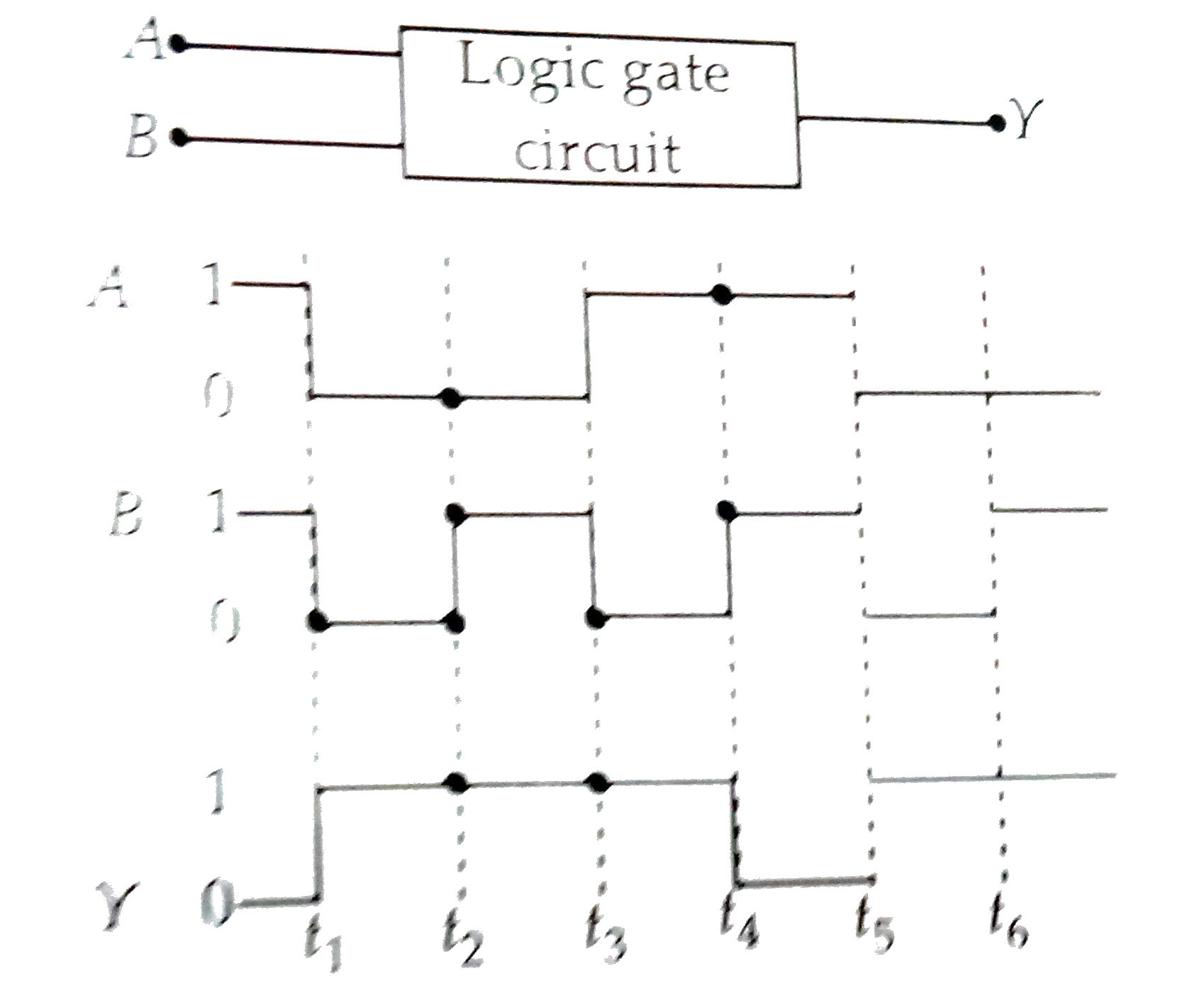
The logic gate isANOR gateBOR gateCAND gateDNAND gate
The following figure showns a AND logic gate circuit with two inputs A and B and the output C. The voltage waveforms at C will be -
 View Solution
The following figure shows a logic gate circuit with two inputs A and B and the output Y. The voltage waveforms of A,B and Y are as given :

The logic gate isView SolutionThe following figure shows a logic gate circuit with two inputs A and B output C. The voltage waveforms of A,B and C are as shown in second figure given below :-
_E01_436_Q01.png)
The logic circuit gate is :-View SolutionThe following figure shows a logic gate circuit with two inputs A and B and the output Y. The voltage waveforms of A,B and the output Y are as given
 View Solution
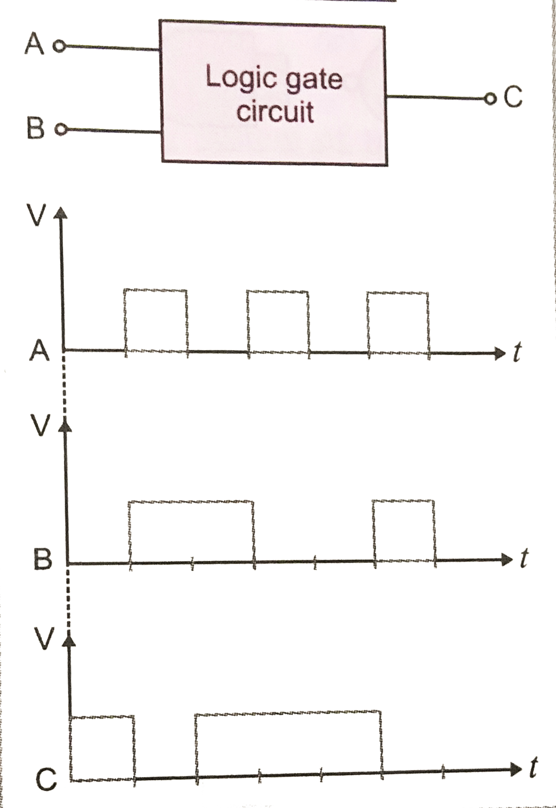
Fig, shows a logic gate circuit with two input A and B and the output C. The voltage wave form of A, B and C are as shown in Fig.The logic gate circuit is
 View Solution

