The figure shows part of an electric circuit. The potential difference is

A
9.0 V
B
7.5 V
C
6.0 V
D
4.5 V.
Text Solution
The correct Answer is:B
|
Topper's Solved these Questions
- MULTIPLE CHOICE QUESTIONSBOOK - NAVNEET PUBLICATION - MAHARASHTRA BOARDCHAPTER - MULTIPLE CHOICE QUESTIONSEXERCISE - Magnetic Effect of Electric Current
4 Videos
- MULTIPLE CHOICE QUESTIONSBOOK - NAVNEET PUBLICATION - MAHARASHTRA BOARDCHAPTER - MULTIPLE CHOICE QUESTIONSEXERCISE - Magnetism
5 Videos
- MULTIPLE CHOICE QUESTIONSBOOK - NAVNEET PUBLICATION - MAHARASHTRA BOARDCHAPTER - MULTIPLE CHOICE QUESTIONSEXERCISE - Electrostatics
5 Videos
- MODEL QUESTION PAPER FOR PRACTICEBOOK - NAVNEET PUBLICATION - MAHARASHTRA BOARDCHAPTER - MODEL QUESTION PAPER FOR PRACTICEEXERCISE - SECTION-D
5 Videos
- QUESTION BANK 2021BOOK - NAVNEET PUBLICATION - MAHARASHTRA BOARDCHAPTER - QUESTION BANK 2021EXERCISE - Semiconductors Devices (Long Answer ( LA) ( 4 marks Each) )
3 Videos
Similar Questions
Knowledge Check
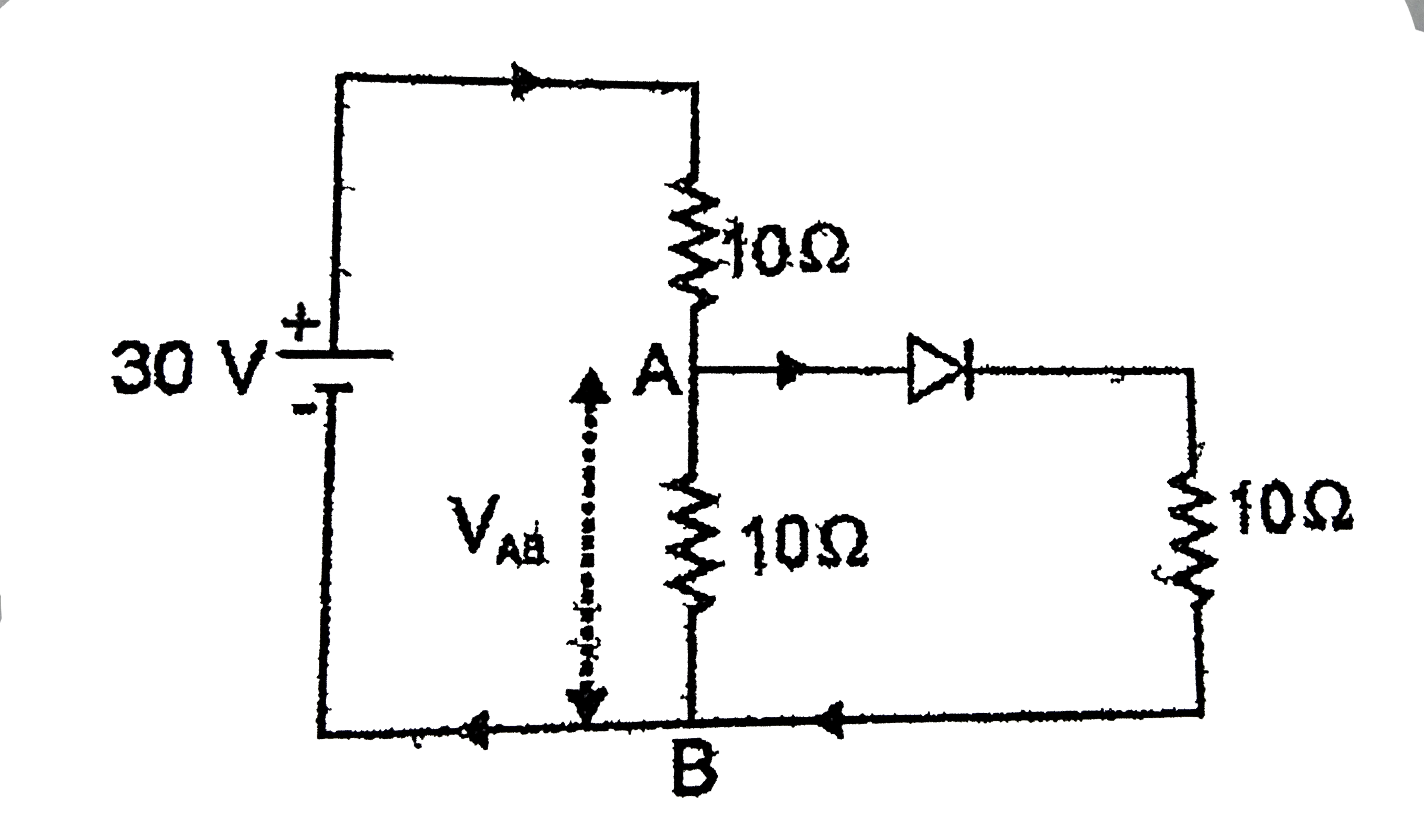
For given circuit potential difference VAB isA10 VB20 VC30 VDnoneIf the figure shows a part of an electric circuit, then the current is
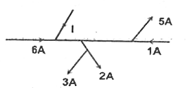 A1AB3AC2 AD4A
In figure two points A and B are located in a region of electric field . The potential difference VB−VA is
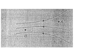 APositiveBNegativeCZeroDNone of these
The following figure shows a part of a circuit,the potential difference between C and B(VC−VB) is
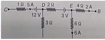
View SolutionIn figure two points A and B are located in a region of electric field . The potential difference VB−VA is

View SolutionFind the potential difference Va−Vbin the circutis shown in figure
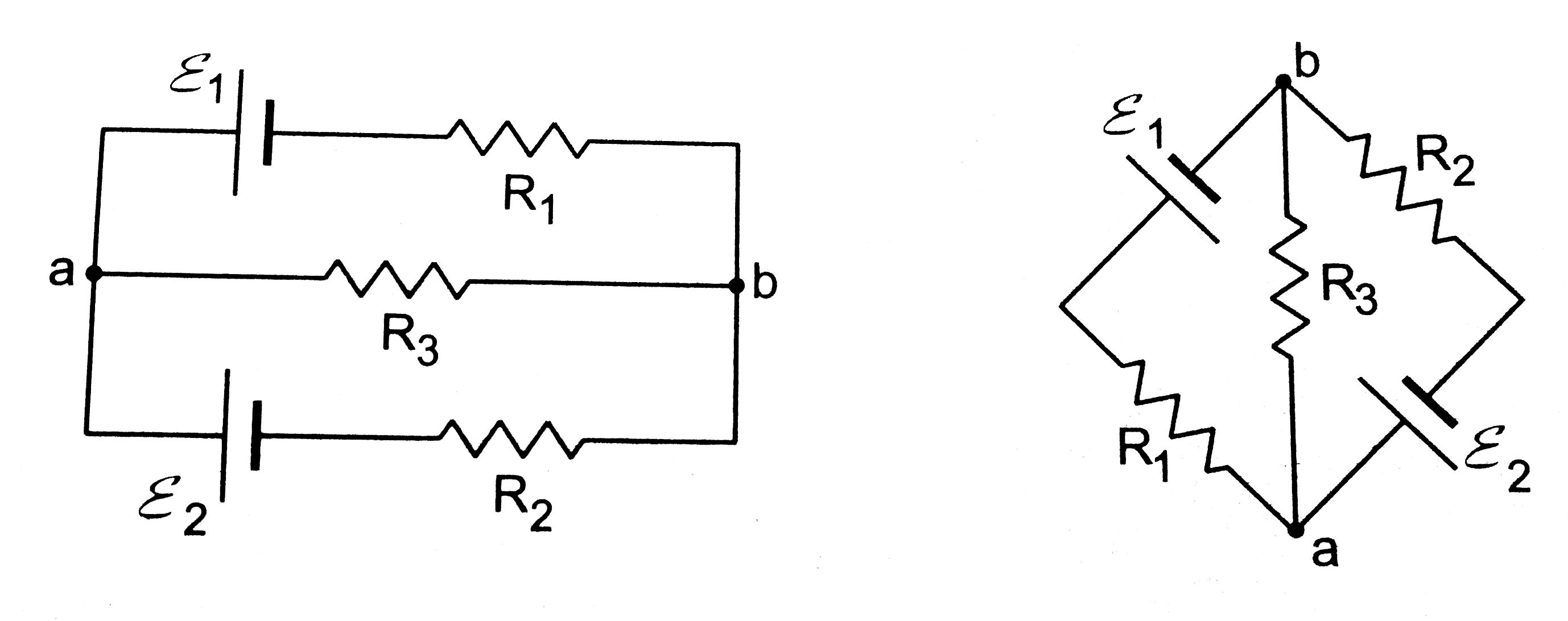
View SolutionThe work done in carrying an electron from point A to a point B in an electric is 10 MJ. The potential difference (VB−VA) is then
View SolutionA current of 2 A flows in an electric circuit as shown in figure. The potential difference (VR−VS), in volts (VE and VS are potenitals at R and S respectively) is
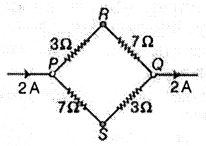
View Solution
