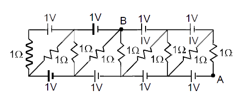
Find the potential difference Va−Vbin the circutis shown in figure
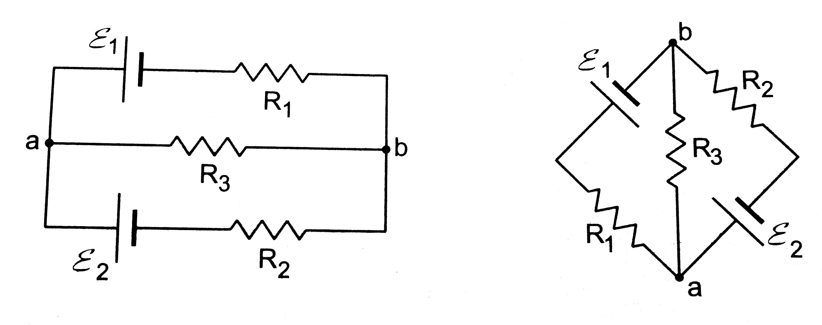
In circuit ab baa
E2+iR2+iR3=0
iR2+i1R3=−E2
⇒iR2R1+iR3R1=−E2R1 ……..(1)
andi1R3+E1−(i−i1)R1=0
E1=i1(R1+R3)−iR1
⇒(E1)(R2)=iRi(R2)+(i1)(R2)(R3)−i(R1)(R2)..........(2)
Add∈g(1)and(2),we≥t
(i1)(R1)(R2)+i1(R3)(R1)+i1(R2)(R−3)
=E1R2−E2R1
⇒i1((R3)(R1)+(R2)(R1)+(R2)(R3))
(E1)(R2)−(E2)(R−1)
i1=((E1)(R2)−(E2)R1R3(R1)+(R2)(R1)+(R2)(R3))
Va−Vb=((E1)(R2)−(E2)R1R3(R1)+(R2)(R1)+(R2)(R3))R3)
=((E1)(R2)(R3)−(E2)(R1)R3R3(R1)+(R3)(R1)+(R2)(R3))
=⎡⎢
⎢⎣E1R2−E2R1(1R2)+(1R1)+(1R3)⎤⎥
⎥⎦
(b) Same as a .
Topper's Solved these Questions
- ELECTRIC CURRENT IN CONDUCTORSBOOK - HC VERMACHAPTER - ELECTRIC CURRENT IN CONDUCTORSEXERCISE - Objective 2
9 Videos
- DISPERSION AND SPECTRABOOK - HC VERMACHAPTER - DISPERSION AND SPECTRAEXERCISE - Exercises
11 Videos
- ELECTRIC CURRENT THROUGH GASESBOOK - HC VERMACHAPTER - ELECTRIC CURRENT THROUGH GASESEXERCISE - Exercises
23 Videos
Similar Questions
Knowledge Check
Find VP−VQ in the circuit shown in figure.
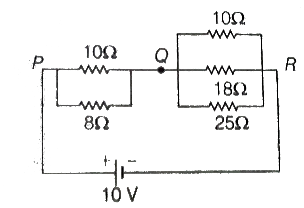 A6.68 VB8 VC4.65 VD7 V
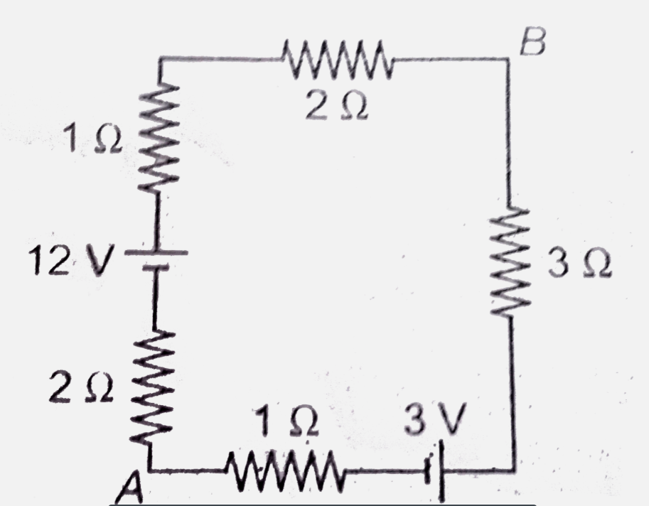
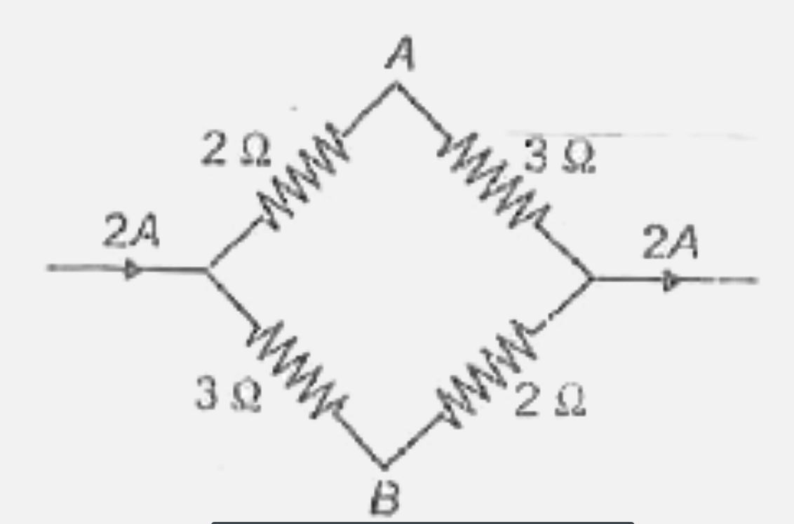
Potential difference VA−VB in the network shown in
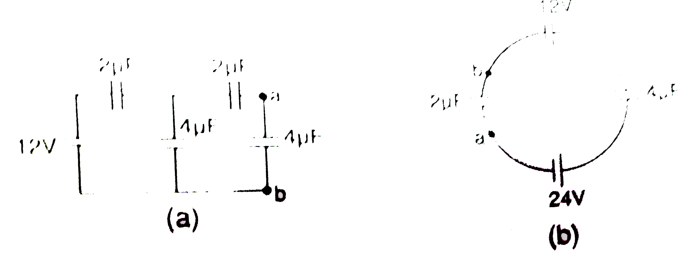
View SolutionFind the potential difference Va−Vb between the points a and b shown in each part of the figure.
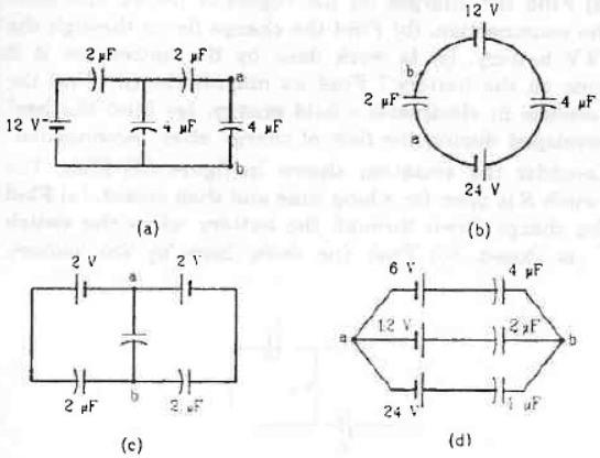
View SolutionFind the potential difference Va−Vb between the points a and b shown in each part of the figure.
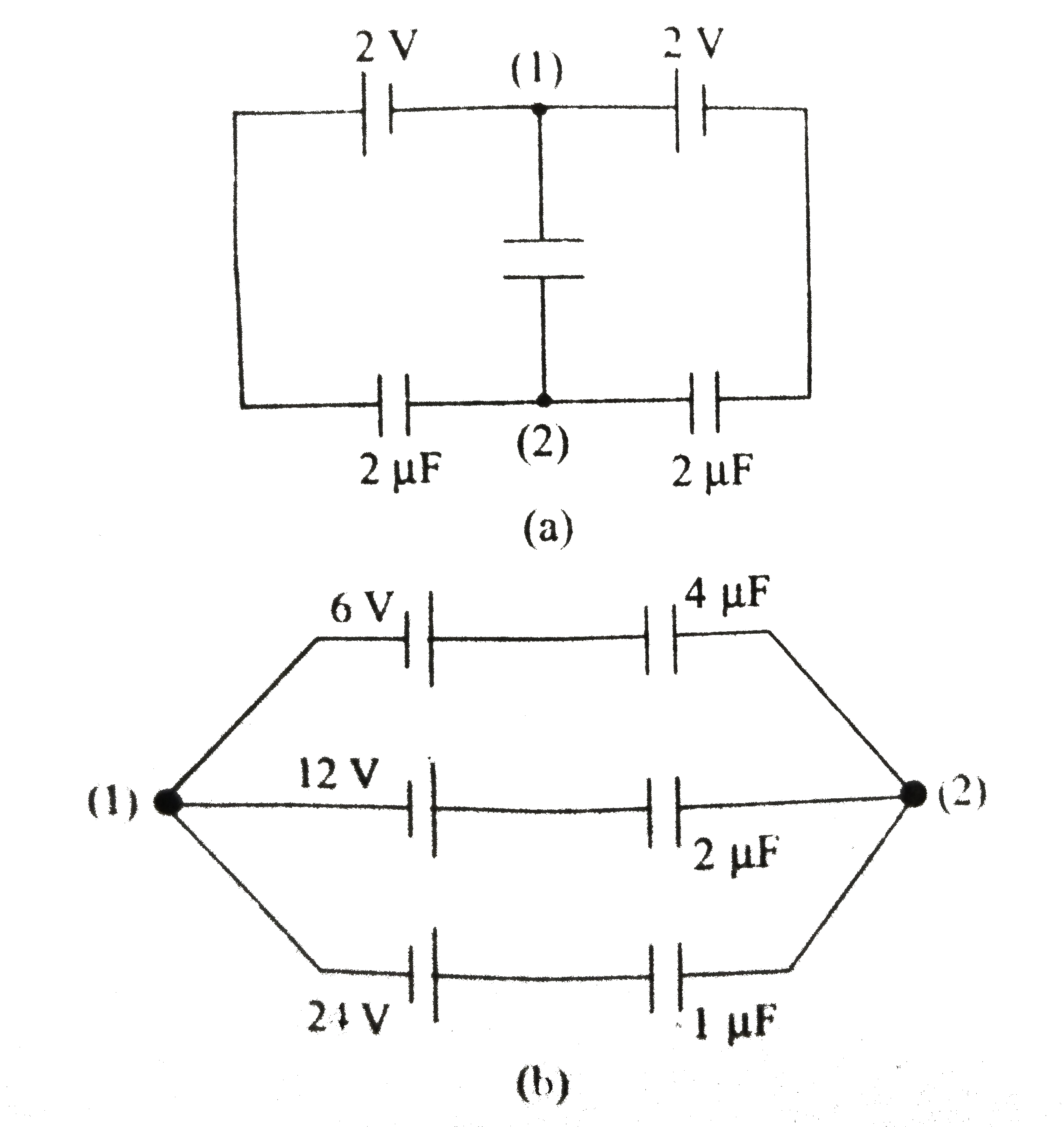
View SolutionFind the potential difference Va−Vb between the points (1) and (2) shown in each part of Fig.
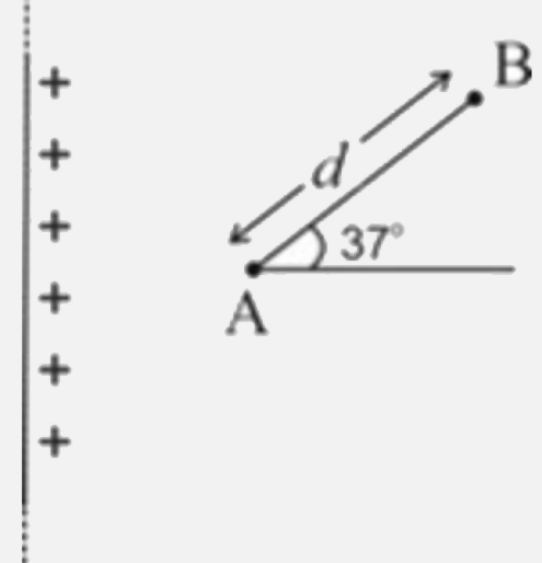
View SolutionAn infinite thin non - conducting sheet has uniform surface charge density σ. Find the potential difference VA−VB between points A and B as shown in the figure. The line AB makes an angle of 37∘ with the normal to the sheet. (sin37∘=35)
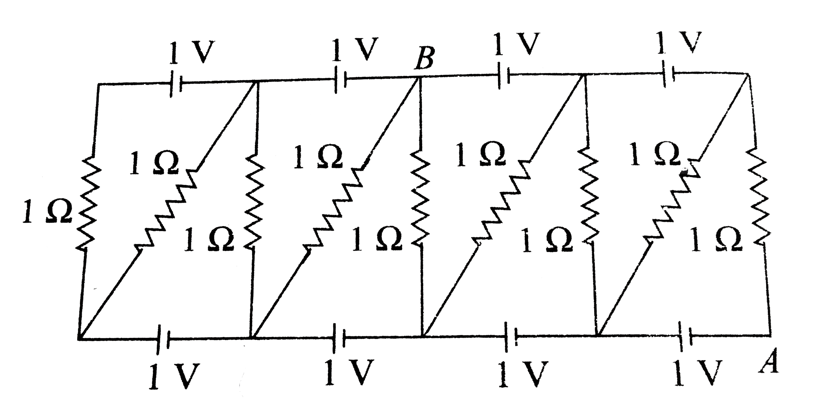
View SolutionThe potential difference VA−VB for the circuit shown in fig. is. −(22/x)V. find the value of x.
View Solution(a) Figure 24-10a shows two points i and fin a uniform electric field →E. The points lie on the same electric field line (not shown) and are separated by a distanced. Find the potential difference Vf−Vi by moving a positive test charge q0 from i to f along the path shown, which is parallel to the field direction.
(b) Now find the potential difference Vf−Vi by moving the positive test charge q0 from i to f along the path icf shown in Fig. 24-10b.
View Solution

