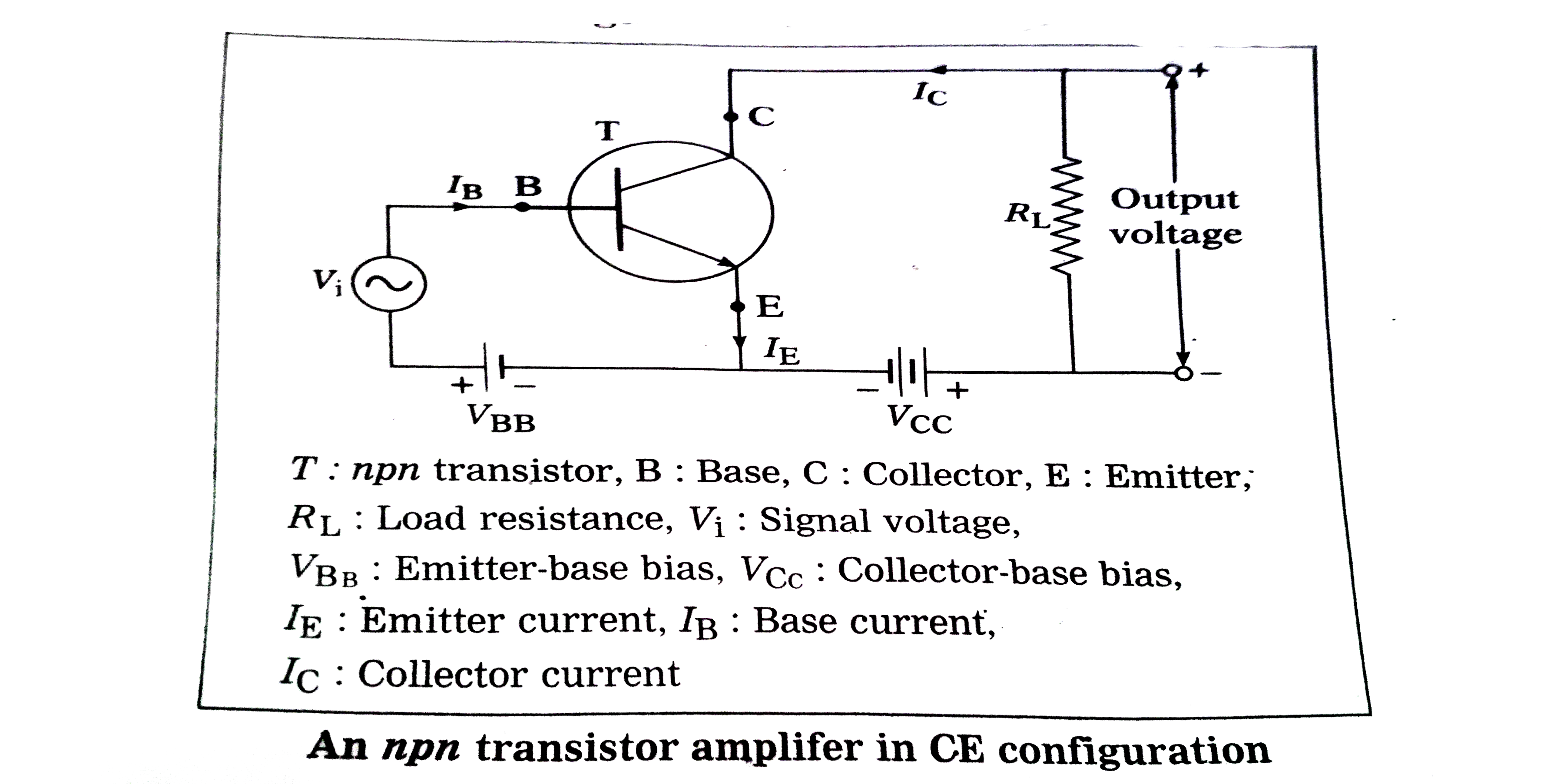
With the help of a labelled circuit diagram, explain how an n-p-n transistor can be used as an amplifier in common-emitter configuration. Explain how the input and output voltages are out of phase by 180 for a common-emitter transistor amplifier.
Principle : The collector current in a transistor can be controlled by a small change in the base current.
Electric ciruit : Consider the use of pnp transistor as an amplifier in the common-emitter (CE) configuration in which the emitter is common to the input and output circuit. The emitter-base junction is forward blased by the battery while the collector-base junction is reverse biased by the battery
The signal voltage to the amplified is applied between the base and the emitter.
Working : The conductor characterisitics shows that in the active region. the collector current is determined almost entirely by the base current , and collector potential has relatively little effect on it.
The applied signal voltage causes small changes in the emitter-base p.d. thereby producing variations in the base current. These cause proportionately larger variations in the collector current because where the common-emitter current gain ( is always greater than 50 .

The time-varying collector current produces a time-varying output voltage across the load resistance .
Thus, , so that the circuit has produced a voltge gain. The amplifier's voltage gain is defined as the ratio of the input voltage to the input voltage.
Topper's Solved these Questions
- INSTRUMENTS : CONSTRUCTION AND WORKING BOOK - NAVNEET PUBLICATION - MAHARASHTRA BOARDCHAPTER - INSTRUMENTS : CONSTRUCTION AND WORKING EXERCISE - Electrons and photons
1 Videos
- EXPLANATION, CHARACTERISTICS AND PROPERTIES BOOK - NAVNEET PUBLICATION - MAHARASHTRA BOARDCHAPTER - EXPLANATION, CHARACTERISTICS AND PROPERTIES EXERCISE - Assignments
2 Videos
- LAWS AND THEORIESBOOK - NAVNEET PUBLICATION - MAHARASHTRA BOARDCHAPTER - LAWS AND THEORIESEXERCISE - Assignments
2 Videos
Similar Questions
Knowledge Check
In a common emitter amplifier, the input and output voltage are out of phase by
A30°B90°C120°D180°If a transistor is used in common -emitter mode as an amplifier,then
Athe base -collector junction is forward biasedBthe base -emitter junction is reverse biasedCthe input signal is connected in series with the voltage applied to the base -emitter junctionDthe input signal is connected in series with the voltage applied to the base -collector junction
With a neat labelled diagram, explain the actionn of npn transistor in common base configuration
View SolutionDraw circuit diagram for n-p-n transistor to draw input and output characteristics in common base configuration. Draw the input and ouput curves and explain them.
View SolutionDraw the circuit diagram of a common emitter transistor amplifier. Write the expression for its voltage gain. Explain , how the input and output signal differ in phase by 180∘
View SolutionWith the help of a labelled circuit diagram, explain how an n-p-n transistor can be used as an amplifier in common-emitter configuration. Explain how the input and output voltages are out of phase by 180 for a common-emitter transistor amplifier.
View SolutionDerive relation between current gain in common base and common-emitter transistor amplifiers.
View SolutionWhat is the phase relationship in the output and input voltage in the common base transistor amplifier.
View Solution
