Figure shows a typical circuit for low-pass filter. An AC input Vi=10mV is applied at the left end and the output V0 is received at the right end. Find the output voltages for v=10kHz,100kHz,1.0MHzand10.0MHz. Note that as the frequency is increased the output decreases and hence the name low-pass filter.

Here V1=10×10−3V,
R=1×10³Ω,
C=10×10(−9)F
(a) XC=1ωC=12πfC
=12π×10×103×10×10−9<br>=(1)/(2pi xx 10^-4) = 10^4/(2pi)=5000/pi<br>Z= sqrt(R^2 + X_c^2)<br>=sqrt((1+10^3) +(500//pi)^2)<br>=sqrt(10^6 + (5000//pi)^2)<br>I_0 = E_0/Z = V_1/Z<br>=(10 xx 10^-3)/(sqrt(10^6 + (5000//pi)^2)<br>V_0=I_0X_c<br>=10^-2/(sqrt(10^5 + (5000//h^2))) xx 5000/pi<br>= 0.00846V=8.46=mV =8.5mV<br>X_c=(1)/(omegaC) = (1)/(2pifc)<br>=(1)/(2pi xx 10^5 xx 10 xx 10^-9)<br>(1)/(2pi10^-3)<br>=(10^3)/(2pi) = (1000)/(2pi) = (500)/(pi)<br>Z=sqrt(R^2 + X_c^2)<br>=sqrt((10^3)^2 + (500//pi)^2)<br>I_0 = E_0/Z = V_1/Z<br>=(10 xx 10^3)/(sqrt(10^5 + (500//pi)^2)<br>V_0=I_0 X_c<br>=(10^2)/(sqrt(10^5 + (50//pi)^2)) xx (500)/(pi)<br>=1.6124 V= 1.6 mV<br>(c)f=1 MHz = 10^6 Hz<br>X_c = (1)/(omegaC)=(1)/(2pifC)<br>=(1)/(2pi xx 10^6 xx 10^-9 xx 10)<br>=1/(2pi xx 10^-2) = 100/ (2pi) = 500 /pi<br>Z=sqrt(R^2 + X^2C)<br>=sqrt((10^3)^2 +(50//pi)^2)<br>I_0 = E_0/Z = V_1/Z<br>=(10 xx 10^-3)/sqrt(10^6 +(50//pi)^2)<br>V_0 = I_0X_C<br>=(10^-2)/(sqrt(10^5 +(50//pi)^2)) xx 50/pi<br>=0.16 mV<br>(d)f=10 MHz<br>=10 xx 10^6 Hz = 10^7 Hz<br>X_c=(1)/(omegaC)= (1)/(2pifC)<br>=(1)/(2pi xx 10 ^7 xx 10 xx 10 ^-9) = 5/pi<br>Z=sqrt(R^2 + X_c^2)<br>=sqrt((10^3)^2 + (5//pi)^2)<br>i_0 = E_0/2 = V_1/Z<br>=(10 xx 10^-3)/sqrt(10^6 + (5//pi)^2)<br>V_0 = I_0X_C<br>=(10^-2)/(sqrt(10^6 +(5//pi)^2)) xx 5/pi = 16 mu V.
Topper's Solved these Questions
Similar Questions
An a.c. supply if 230V is applied to a half wave rectifier circuit through a transformer of turn ratio 10:1. Find the output d.c. voltage. Assume the diode to be ideal.
View SolutionA capacitor of capacitance 10μF is connected to an oscillator giving an output voltage ε=(10V)sinωt. Find the peak currents in the circuit for ω=10s−1,100s−1,500s−1,1000s−1.
View Solution
Knowledge Check
An input voltage Vi of 0.20V is applied to an operational amplifier connected as shown in the diagram. What is the output voltage V0?
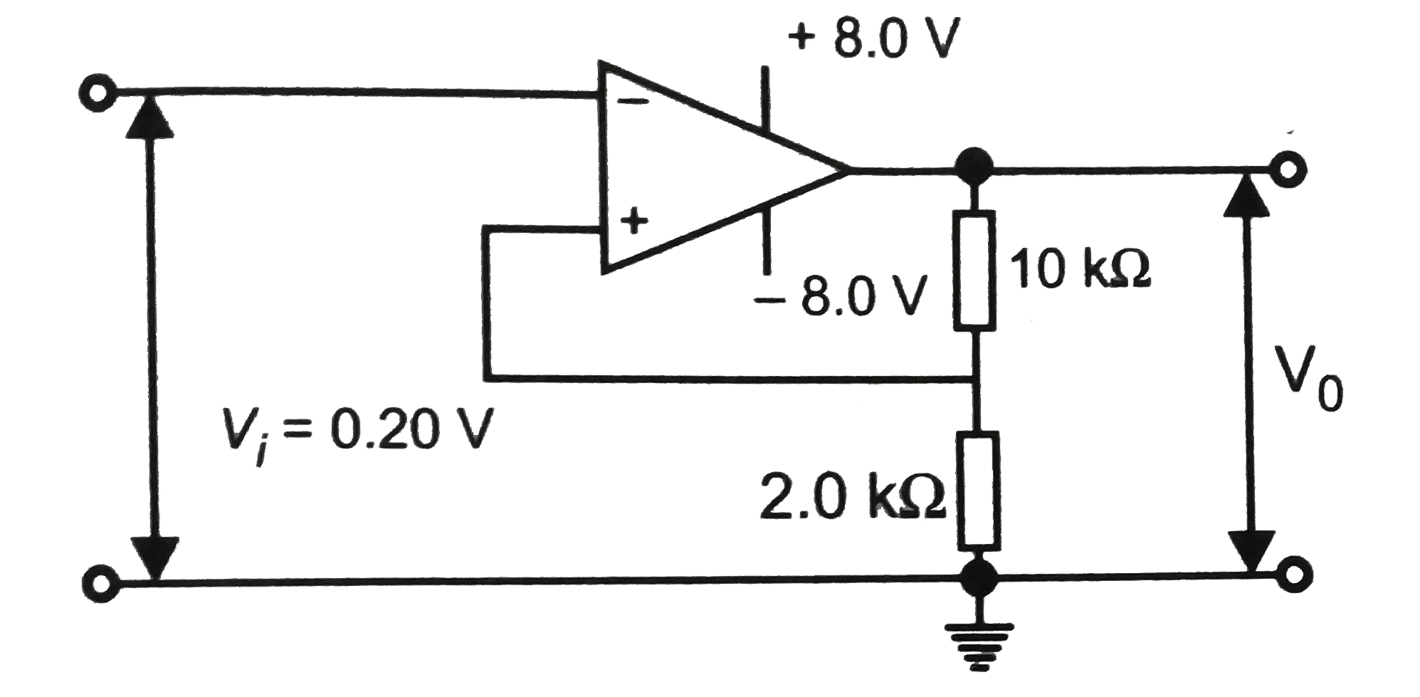 A0.20VB1.2VC0.80VD8.0V
The figure below shows a circuit and its input voltage vi as function of time t.
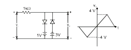
Assuming the diodes to be ideal, which of the following graphs depicts the output voltage v0 as function of time t ?A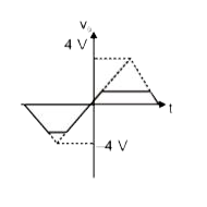 B
B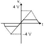 C
C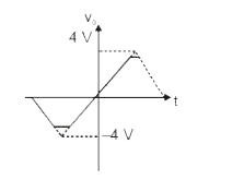 D
D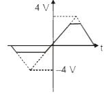

In p-n junction diode a square input signal of 10 V is applied as shown in figure The output signal across RL will beA B
B C
C D
D
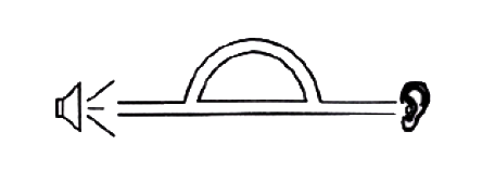
Figure shows a tube structure in which a sound signal is sent from one end and is received at the other end. The semicircular part has a radius of 10.0 cm. The frequency of the sound source can be varied from 1 to 10 kHz. Find the frequencies at which the ear perceives maximum intensity. The speed of sound in air =342m/s
View Solution
In p-n junction diode a square input signal of 10 V is applied as shown in figure The output signal across RL will be
View SolutionThe peak voltage in the output of a half-wave diode rectifier fed with a sinusiodal signal without filter is 10V. The dc component of the output voltage is
View SolutionThe peak voltage in the output of a half-wave diode rectifier fed with a sinusiodal signal without filter is 10V. The dc component of the output voltage is
View SolutionA common emitter amplifier gives an output of 3 V for an input of 0.01 V. If β of the resistance is 100 and the input resistance is 1kΩ. then the collector resistance is
View Solution
