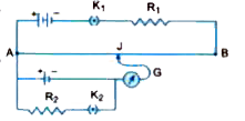
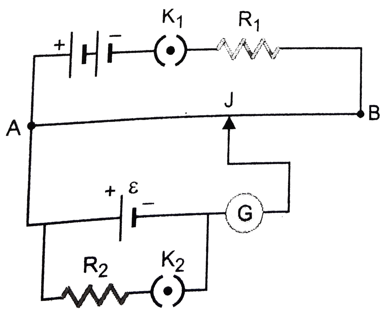
(a) For the circuit shown in the figure, how would the balancing length be affected, if (i) R1 is decreased, (ii) R2 is increased, the other factors remaining the same in the circuit ? Justify your answer in each case.
(b) Why is a potentiometer preferred over a voltmeter ? Give reason.

(a) (i) When R1 is decreased, the current flowing in the potentiometer wire AB and consequently the potential gradient along the potentiometer wire increases. As a result, the balancing length decreases i.e., the balancing point shifts towards left (towards point A).
(ii) When R2 is increased, the current flowing through R2 decreases and as a result the potential difference across the terminals of the cell, whose internal resistance is to be determined, increases [V=ε−Ir] . As a result, the balancing length increases, i.e., the balancing point shifts towards right (towards the point B).
(b) A potentiometer is preferred over a voltmeter for measuring potential differences and emf of cells because measurement is done here in balance condition, when no current is being drawn from the given cell.
Topper's Solved these Questions
- BOOK - U-LIKE SERIESCHAPTER - CURRENT ELECTRICITY EXERCISE - LONG ANSWER QUESTIONS - II8videos
CURRENT ELECTRICITY
- BOOK - U-LIKE SERIESCHAPTER - CURRENT ELECTRICITY EXERCISE - SELF ASSESSMENT TEST (SECTION A (MULTIPLE CHOICE QUESTIONS))6videos
CURRENT ELECTRICITY
- BOOK - U-LIKE SERIESCHAPTER - CURRENT ELECTRICITY EXERCISE - SHORT ANSWER QUESTIONS42videos
CURRENT ELECTRICITY
- BOOK - U-LIKE SERIESCHAPTER - CBSE SAMPLE QUESTION PAPER 2019-20 (SOLVED)EXERCISE - SECTION D6videos
CBSE SAMPLE QUESTION PAPER 2019-20 (SOLVED)
- BOOK - U-LIKE SERIESCHAPTER - DUAL NATURE OF RADIATION AND MATTEREXERCISE - SELF ASSESSMENT TEST SECTION-C (VERY SHORT ANSWER QUESTIONS)3videos
DUAL NATURE OF RADIATION AND MATTER
Similar Questions
For the circuit would the balancing length increase, decrease or remain the same if (i) R1 is decreased (ii) R2 is increased, without any change (in each case) in the rest of the circuit ? Justify your answer in each case.
 View Solution
For the circuit would the balancing length increase, decrease or remain the same if
(i) R1 is decreased
(ii) R2 is increased, without any change (in each case) in the rest of the circuit ?
Justify your answer in each case.
 View Solution
Knowledge Check
- Question 1 - Select One
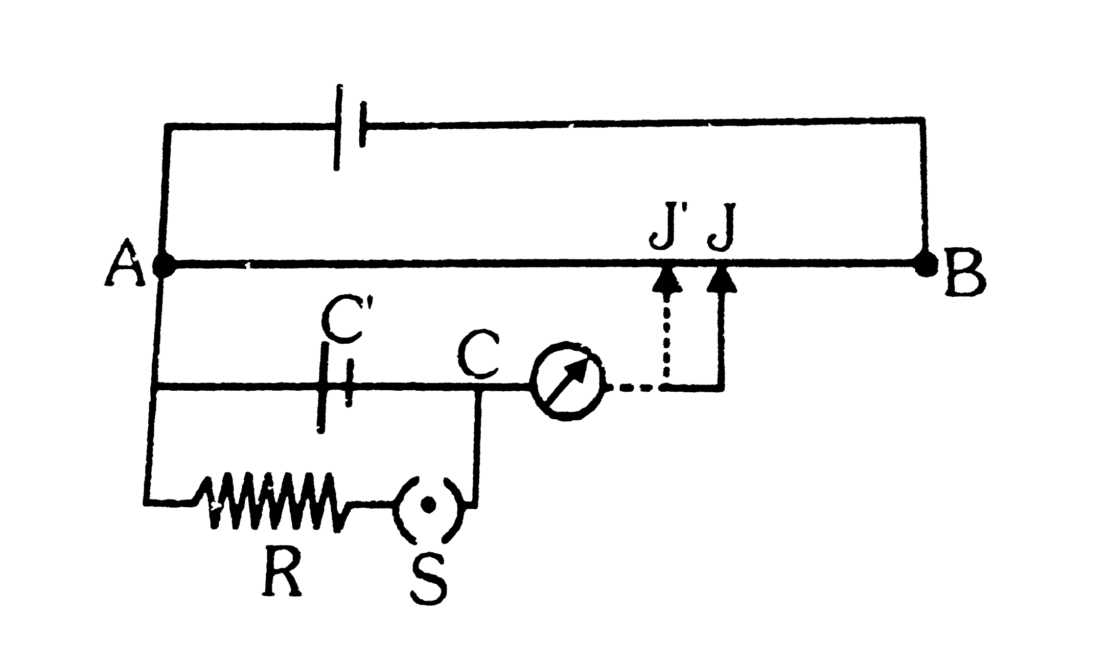
In the potentiometer circuit shown in the figure the balance length AJ=60cm when switch S is open. When switch S is closed and the value of R=5Ω, the b alance length AJ=50cm. The internal resistance of the cell C' is
 A1.2ΩB1.0ΩC0.8ΩD0.6Ω
 - Question 2 - Select One
For the circuit shown in the figure. The equivalent resistance between point A and B for the two cases (i) VA>VB,(ii)VB>VA respectively is……….Ωand……….Ω respectively. (D1andD2 are ideal diodes)
A25,∞B50,∞C∞,25D25,25
In the potentiometer circuit shown in the figure the balance length AJ=60cm when switch S is open. When switch S is closed and the value of R=5Ω, the b alance length AJ=50cm. The internal resistance of the cell C' is
 View Solution
A wire of length L and resistance R is stretched so that its length is doubled and the area of cross-section is halved. How will its:
(a) resistance change?
(b) resistivity change?
Justify your answer in each case.View SolutionIf we increase the driving frequency in a circuit with a purely resistive load, do (a) amplitude VR and (b) amplitude IR increase , decrease, or remain the same ?
View SolutionHow is mutual inductance of a pair of coils affected when (i) separation between the coils in increased, (ii) the number of turns of each coil is increased , (iii) a thin iron sheet is placed between the two coils, other factors remaining the same ? Explain your answer in each case.
View SolutionHow is mutual inductance of a pair of coils affected when (i) separation between the coils in increased, (ii) the number of turns of each coil is increased , (iii) a thin iron sheet is placed between the two coils, other factors ramaining the same ? Explain your answer in each case.
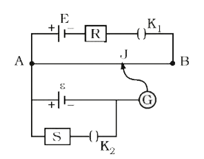
View SolutionTwo students ‘X’ and ‘Y’ perform an experiment on potentiometer separately using the circuit given: Keeping other parameters unchanged, how will the position of the null point be affected it
(i) X’ increases the value of resistance R in the set-up by keeping the key K1 closed and the key K2 open?
(ii) Y’ decreases the value of resistance S in the set-up, while the key K2 remain open and the key K1 closed? Justify.
 View Solution

