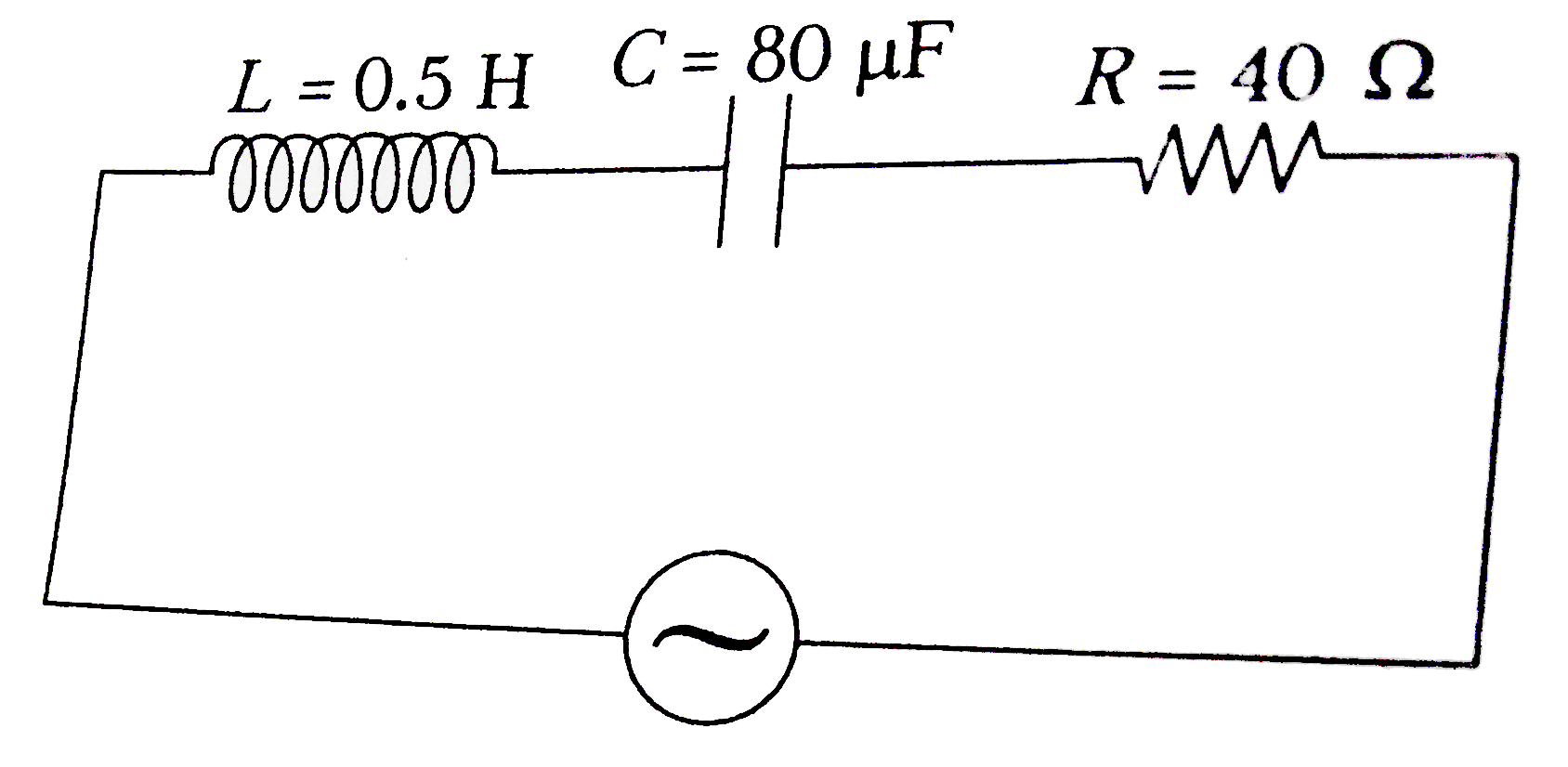
(a) In a series LCR circuit connected across an AC source of variable frequency, obtain the expression for its impedance and draw a plot showing its variation with frequency of the AC source.
(b) What is the phase difference between the voltages across inductor and the capacitor at resonance in the LCR circuit ?
(c ) When and inductor is connected to a 200 V DC voltage, a current of 1Aflows trough it. when the same inductor is connected to a 200 V, 50 Hz AC source, only 0.5 A current flows. Explain, why ? Also, calculate the self inductance of the inductor.
Solution:
(a) To derive the expression for the impedance Z in a series LCR circuit connected to an AC source, we start with the definitions of the voltages across the resistor, inductor, and capacitor.
1. Voltage across the Resistor VR:
VR=ImR
where Im is the maximum current and R is the resistance.
2. Voltage across the Inductor VL:
VL=ImXL=Im(Lω)
where XL=Lω is the inductive reactance and ω is the angular frequency.
3. Voltage across the Capacitor VC:
VC=ImXC=Im(1Cω)
where XC=1Cω is the capacitive reactance.
4. Phasor Diagram:
- The voltage across the resistor VR is in phase with the current.
- The voltage across the inductor VL leads the current by 90∘.
- The voltage across the capacitor VC lags the current by 90∘.
5. Resultant Voltage:
The total voltage V can be expressed using the phasor sum:
V=VR+(VL−VC)
Since VL and VC are out of phase, we can express the impedance as:
Z=√R2+(XL−XC)2
where XL−XC=Lω−1Cω.
6. Final Expression for Impedance:
Z=√R2+(Lω−1Cω)2
7. Graph of Impedance vs Frequency:
- The impedance Z varies with frequency, decreasing to a minimum at resonance where XL=XC (i.e., ω=1√LC).
- The graph will show a U-shaped curve with a minimum at resonance.
(b) At resonance in an LCR circuit:
- The inductive reactance XL equals the capacitive reactance XC.
- Therefore, the phase difference ϕ between the voltages across the inductor and capacitor is:
ϕ=180∘
This means that the voltages cancel each other out at resonance.
(c) When the inductor is connected to a 200 V DC supply:
1. The current I=1A flows through it.
- Using Ohm's law:
R=VI=200V1A=200Ω
2. When the same inductor is connected to a 200 V, 50 Hz AC source:
- The current I=0.5A flows.
- The impedance Z can be calculated:
Z=VI=200V0.5A=400Ω
3. Calculating Self-Inductance L:
- The impedance in AC is given by:
Z=√R2+(XL)2
where XL=Lω and ω=2πf=2π×50Hz.
- Thus, we have:
400=√2002+(L⋅2π⋅50)2
- Squaring both sides:
160000=40000+(L⋅100π)2
- Rearranging gives:
(L⋅100π)2=120000
- Taking the square root:
L⋅100π=√120000⟹L=√120000100π
- Simplifying:
L≈346.41314.16≈1.10H
VR=ImR
where Im is the maximum current and R is the resistance.
VL=ImXL=Im(Lω)
where XL=Lω is the inductive reactance and ω is the angular frequency.
VC=ImXC=Im(1Cω)
where XC=1Cω is the capacitive reactance.
- The voltage across the resistor VR is in phase with the current.
- The voltage across the inductor VL leads the current by 90∘.
- The voltage across the capacitor VC lags the current by 90∘.
The total voltage V can be expressed using the phasor sum:
V=VR+(VL−VC)
Since VL and VC are out of phase, we can express the impedance as:
Z=√R2+(XL−XC)2
where XL−XC=Lω−1Cω.
Z=√R2+(Lω−1Cω)2
- The impedance Z varies with frequency, decreasing to a minimum at resonance where XL=XC (i.e., ω=1√LC).
- The graph will show a U-shaped curve with a minimum at resonance.
- The inductive reactance XL equals the capacitive reactance XC.
- Therefore, the phase difference ϕ between the voltages across the inductor and capacitor is:
ϕ=180∘
This means that the voltages cancel each other out at resonance.
1. The current I=1A flows through it.
- Using Ohm's law:
R=VI=200V1A=200Ω
- The current I=0.5A flows.
- The impedance Z can be calculated:
Z=VI=200V0.5A=400Ω
- The impedance in AC is given by:
Z=√R2+(XL)2
where XL=Lω and ω=2πf=2π×50Hz.
- Thus, we have:
400=√2002+(L⋅2π⋅50)2
- Squaring both sides:
160000=40000+(L⋅100π)2
- Rearranging gives:
(L⋅100π)2=120000
- Taking the square root:
L⋅100π=√120000⟹L=√120000100π
- Simplifying:
L≈346.41314.16≈1.10H
Topper's Solved these Questions
- XII BOARDSBook:XII BOARD PREVIOUS YEAR PAPER ENGLISHChapter:XII BOARDSExercise:SET-I (SECTION-A)
Explore 4 Videos
- XII BOARDSBook:XII BOARD PREVIOUS YEAR PAPER ENGLISHChapter:XII BOARDSExercise:SET-I (SECTION-B)
Explore 5 Videos
- XII BOARDSBook:XII BOARD PREVIOUS YEAR PAPER ENGLISHChapter:XII BOARDSExercise:Section-E
Explore 17 Videos
- SAMPLE PAPER 2019Book:XII BOARD PREVIOUS YEAR PAPER ENGLISHChapter:SAMPLE PAPER 2019Exercise:SECTION D
Explore 6 Videos
Similar Questions
In series LCR circuit, the phase difference between voltage across L and voltage across C is
View SolutionIn a series LCR circuit, operated with an ac of angular frequency ω , the total impedance is
View SolutionIn a series LCR circuit, obtain an expression for the resonant frequency.
View SolutionIn a series L, R, C, circuit which is connected to a.c. source. When resonance is obtained then net impedance Z will be
View SolutionCan the peak voltage across the inductor be greater than the peak voltage of the source in an LCR circuit?
View SolutionFor an LCR series circuit with an ac source of angular frequency ω.
View SolutionA 0.7 henry inductor is connected across a 120V−60HzAC source. The current in the inductor will be very nearly
View SolutionIn the given figure , a series L-C-R circuit is connected to a variable frequency source of 230 V . The impedance and amplitude of the current at the resonating frequency will be

View SolutionA series LCR circuit, has equal resistance capacitive reactance. What is the phase angle between voltage across generator and resistor ?
View SolutionIn series LCR AC circuit, the voltage of the source at any instant is equal to
View Solution