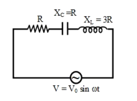
A voltage V=V0sinωt is applied to a series LCR circuit. Derive expression for the average power dissipated over a cycle.
Under What condition (i) no power is dissipated even though the current flows through the circuit?
(ii) Maximum power is dissipated in the circuit?
To derive the expression for the average power dissipated over a cycle in a series LCR circuit with a voltage V=V0sin(ωt), we follow these steps:
Step 1: Write the expression for instantaneous power
The instantaneous power P(t) in the circuit can be expressed as:
P(t)=I2R
where I is the current flowing through the circuit and R is the resistance.
Step 2: Find the expression for current
The current I in the circuit can be expressed in terms of the applied voltage and impedance Z:
I=VZ=V0sin(ωt)Z
Substituting this into the power expression gives:
P(t)=(V0sin(ωt)Z)2R=V20Rsin2(ωt)Z2
Step 3: Calculate average power over one cycle
To find the average power Pavg over one complete cycle, we need to integrate the instantaneous power over one period T=2πω:
Pavg=1T∫T0P(t)dt=1T∫2πω0V20Rsin2(ωt)Z2dt
Using the identity sin2(θ)=1−cos(2θ)2, we can rewrite the integral:
Pavg=V20R2Z2T∫2πω0(1−cos(2ωt))dt
The integral of 1 over one period is T and the integral of cos(2ωt) over one period is zero:
∫2πω01dt=2πω,∫2πω0cos(2ωt)dt=0
Thus, we have:
Pavg=V20R2Z2⋅ω2π
This simplifies to:
Pavg=V20R2Z2
Step 4: Relate average power to RMS values
Using the definitions of RMS voltage and current, we can express the average power as:
Pavg=VrmsIrmscos(ϕ)
where ϕ is the phase difference between the voltage and current, given by:
cos(ϕ)=RZ
Thus, the average power can also be expressed as:
Pavg=VrmsIrmscos(ϕ)
Conditions for power dissipation
1. No power is dissipated even though the current flows through the circuit: This occurs when ϕ=π2 (or 90 degrees), which means cos(ϕ)=0. In this case, the circuit behaves like a purely reactive circuit (inductive or capacitive), and the current is out of phase with the voltage.
2. Maximum power is dissipated in the circuit: This occurs when ϕ=0 (or 0 degrees), which means cos(ϕ)=1. In this case, the circuit behaves like a purely resistive circuit, and the voltage and current are in phase.
Summary
The average power dissipated in a series LCR circuit is given by:
Pavg=VrmsIrmscos(ϕ)
- No power is dissipated when ϕ=π2.
- Maximum power is dissipated when ϕ=0.
The instantaneous power P(t) in the circuit can be expressed as:
P(t)=I2R
where I is the current flowing through the circuit and R is the resistance.
The current I in the circuit can be expressed in terms of the applied voltage and impedance Z:
I=VZ=V0sin(ωt)Z
Substituting this into the power expression gives:
P(t)=(V0sin(ωt)Z)2R=V20Rsin2(ωt)Z2
To find the average power Pavg over one complete cycle, we need to integrate the instantaneous power over one period T=2πω:
Pavg=1T∫T0P(t)dt=1T∫2πω0V20Rsin2(ωt)Z2dt
Using the identity sin2(θ)=1−cos(2θ)2, we can rewrite the integral:
Pavg=V20R2Z2T∫2πω0(1−cos(2ωt))dt
The integral of 1 over one period is T and the integral of cos(2ωt) over one period is zero:
∫2πω01dt=2πω,∫2πω0cos(2ωt)dt=0
Thus, we have:
Pavg=V20R2Z2⋅ω2π
This simplifies to:
Pavg=V20R2Z2
Using the definitions of RMS voltage and current, we can express the average power as:
Pavg=VrmsIrmscos(ϕ)
where ϕ is the phase difference between the voltage and current, given by:
cos(ϕ)=RZ
Thus, the average power can also be expressed as:
Pavg=VrmsIrmscos(ϕ)
1. No power is dissipated even though the current flows through the circuit: This occurs when ϕ=π2 (or 90 degrees), which means cos(ϕ)=0. In this case, the circuit behaves like a purely reactive circuit (inductive or capacitive), and the current is out of phase with the voltage.
The average power dissipated in a series LCR circuit is given by:
Pavg=VrmsIrmscos(ϕ)
- No power is dissipated when ϕ=π2.
- Maximum power is dissipated when ϕ=0.
Topper's Solved these Questions
- BOOK - XII BOARD PREVIOUS YEAR PAPER ENGLISHCHAPTER - XII BOARDSEXERCISE - [Set- II]4videos
XII BOARDS
- BOOK - XII BOARD PREVIOUS YEAR PAPER ENGLISHCHAPTER - XII BOARDSEXERCISE - [Set-III]3videos
XII BOARDS
- BOOK - XII BOARD PREVIOUS YEAR PAPER ENGLISHCHAPTER - XII BOARDSEXERCISE - SET-III, DELHI BOARD4videos
XII BOARDS
- BOOK - XII BOARD PREVIOUS YEAR PAPER ENGLISHCHAPTER - SAMPLE PAPER 2019EXERCISE - SECTION D6videos
SAMPLE PAPER 2019
Similar Questions
Knowledge Check
- Question 1 - Select One
In which of following circuits the maximum power dissipation is observed?
APure capacitive circuitBPure inductive circuitCPure resistive circuitDNone of these - Question 2 - Select One
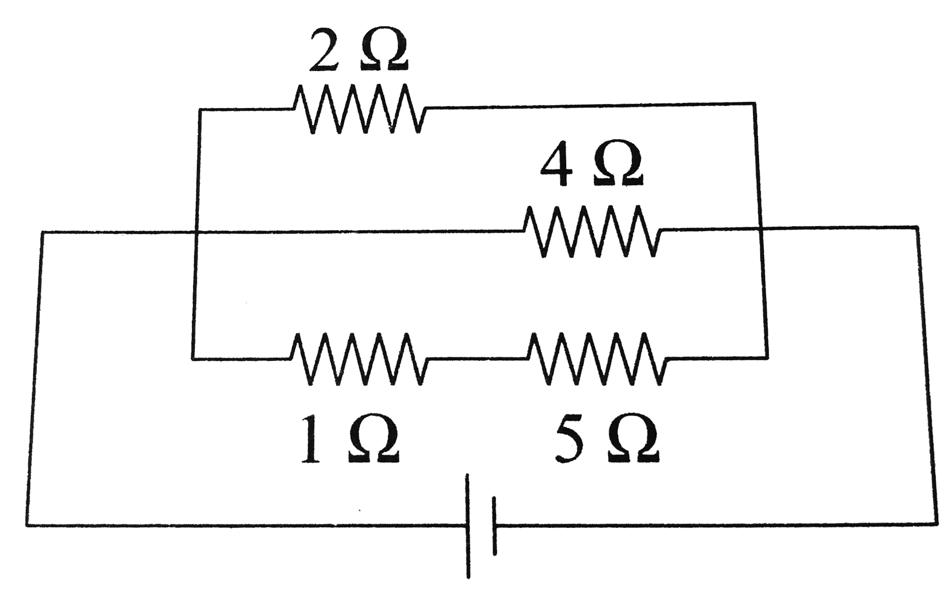
A current of 3A flows through the 2Ω resistor as shown in the circuit. The power dissipated in the 5Ω resistor is
 A5 watt.B4 watt.C2 watt.D1 watt
The average power dissipation in a pure capacitance in AC circuit is
View SolutionIn a LCR series resonating circuit. Give the value of average power loss.
View SolutionIn an AC circuit with voltage V and current I, the power dissipated is
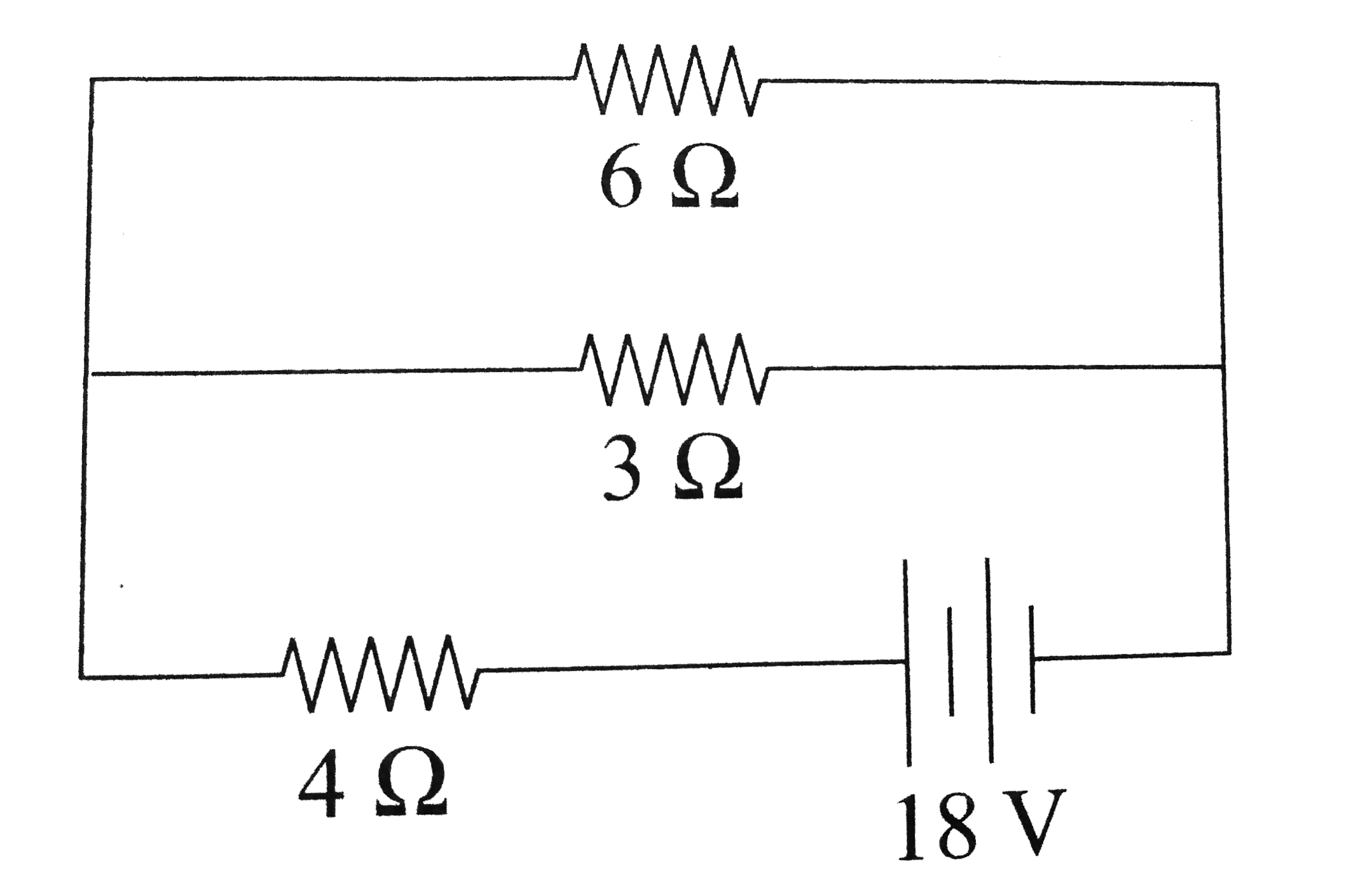
View SolutionThe total power dissipated in watts in the circuit shown here is
 View Solution
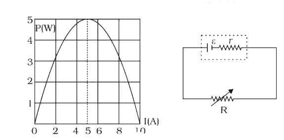
Figure shows the net power dissipated in R versus the current in a simple circuit shown.
 View Solution
In the circuit shown, the average power dissipated in the resistor is (assume diode to be ideal)
View Solution


