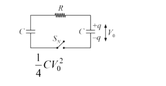
An electric circuit shown in figure has a negligibly small active resistance. The left− hand capacitor was charged to a voltage V0 and then at the moment t=0 the switch Sw was closed. Find the time dependence of the voltages in left and right capacitors.

Initially q1=CV0 and q2=0. After the switch is closed change flows and we get
q1+q2=CV0
q1C+LdIdt−q2C=0 ……..(1)
Also I=.q1=−.q2.Thus
L..I+2IC=0
Hence ..I+ω20I=0 ω20=2LC,
The solution of this equation subject to
I=0 at t=0
is I=I0sinω0t
Integrating q1=A−I0ω0cosω0t
q2=B+I0ω0cosω0t
Finally substituting in (1)
A−BC−2I0ω0Ccosω0t+LI0ω0cosω0t=0
Thus A=B=CV02 and
CV02+I0ω0=0
so q1=CV02(1+cosω0t)
q2=CV02(1−cosω0t)

Topper's Solved these Questions
- OSCILLATIONS AND WAVESBOOK - IE IRODOV, LA SENA & SS KROTOVCHAPTER - OSCILLATIONS AND WAVESEXERCISE - Elastic Waves
39 Videos
- OSCILLATIONS AND WAVESBOOK - IE IRODOV, LA SENA & SS KROTOVCHAPTER - OSCILLATIONS AND WAVESEXERCISE - Electromagnetic Waves, Radiation
36 Videos
- OSCILLATIONS AND WAVESBOOK - IE IRODOV, LA SENA & SS KROTOVCHAPTER - OSCILLATIONS AND WAVESEXERCISE - Electromagnetic Waves, Radiation
36 Videos
- OPTICSBOOK - IE IRODOV, LA SENA & SS KROTOVCHAPTER - OPTICSEXERCISE - Exercise
2 Videos
- PHYSICAL FUNDAMENTALS OF MECHANICSBOOK - IE IRODOV, LA SENA & SS KROTOVCHAPTER - PHYSICAL FUNDAMENTALS OF MECHANICSEXERCISE - Relativistic Mechanics
49 Videos
Similar Questions
Knowledge Check
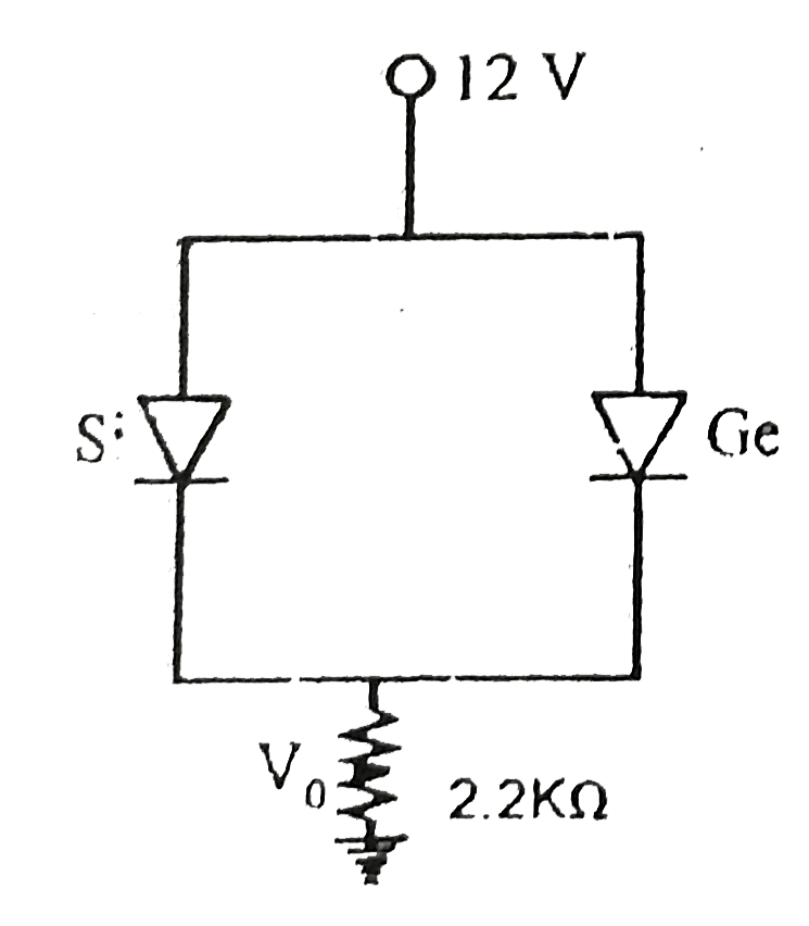
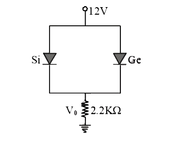
In the circuit shown in figure, Voltage V0 is
 A11.7 voltB11.3 voltC0DNone
In the circuit shown in the figure, the capacitor C is charged to a potential Vo. The heat generated in the circuit when the switch S is closed, is
ACV20B2CV20C4CV20D8CV20At t<0, the capacitor is charged and the switch is opened.At t=0 the switch is closed.The shortest time T at which the charge on the capacitor will be zero is given by:
 Aπ√LCB32π√LCCπ2√LCD2π√LC
An oscillating circuit consists of a capacitor with capacitance C, a coil of inductance L with negligible resistance, and aswitch. With the switch disconnected , the capacitor was charged to a voltage Vm and then at the moment t=0 the switch was closed . Find :
(a) the current (I(t)) in the circuit as a function of time,
(b) the emf of self- inductance in the coil at the moments when the electric energy of the capacitor is equal to that of the current in the coil.
View SolutionIn a circuit shown in fig. the capacitance of each capacitor is equal to C and the resistance, to R One of the capacitor was connected to a voltage V0 and then at the moment t=0 was shorted by means of the swich Sw. Find:
(a) a current I in the circuit as a function of time t:
(b) the amount of generated heat provided a dependence I(t) is known.

View SolutionA circuit consists of a capacitor with capacitance C and a coil of inductance L connected in series, as well as a switch and a resistance equal to the critical value for this circuit. With the switch disconnected, the capacitor was charged to a voltage V0, and at the moment t=0, the switch was closed . Find the corrent I in the circuit as a function of time t.What is Imax equal to ?
View SolutionIn a circuit shown in fig. the capacitance of each capacitor is equal to C and the resistance, to R One of the capacitor was connected to a voltage V0 and then at the moment t=0 was shorted by means of the swich Sw. Find:
(a) a current I in the circuit as a function of time t:
(b) the amount of generated heat provided a dependence I(t) is known.

View SolutionIn a series CR circuit shown in figure,the applied voltage is 10V and the voltage across capacitor is found to be 8V
View Solution


