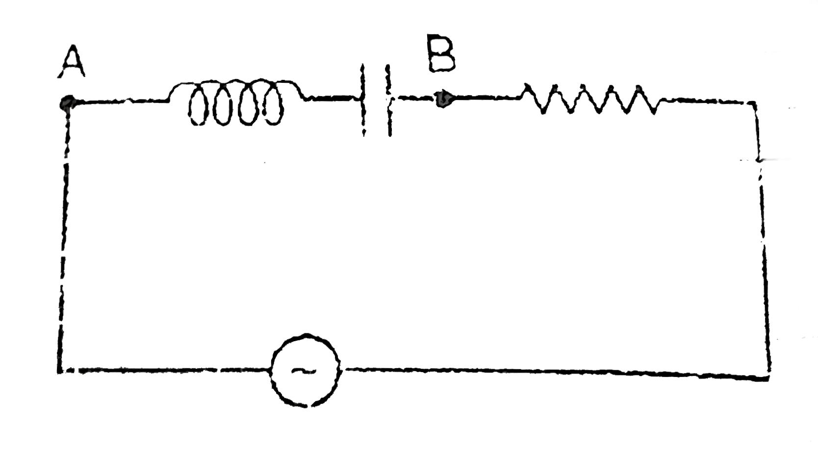
An inductor 200 mH, capacitor 500μF and resistor 10Ω are connected in series with a 100 V variable frequency ac source. What is the frequency at which the power factor of the circuit is unity?
10.22Hz
12.4Hz
19.2Hz
15.9Hz
The correct Answer is:D
To find the frequency at which the power factor of the circuit is unity, we need to analyze the given LCR circuit consisting of an inductor (L), capacitor (C), and resistor (R) connected in series with an AC source.
1. Identify the given values:
- Inductance, L=200mH=200×10−3H
- Capacitance, C=500μF=500×10−6F
- Resistance, R=10Ω
2. Understand the condition for unity power factor:
- The power factor is unity when the circuit is in resonance, which occurs when the inductive reactance (XL) equals the capacitive reactance (XC).
- Mathematically, this is expressed as:
XL=XC
3. Express the reactances:
- The inductive reactance is given by:
XL=ωL=2πfL
- The capacitive reactance is given by:
XC=1ωC=12πfC
4. Set the reactances equal to each other:
2πfL=12πfC
5. Rearranging the equation:
- Multiply both sides by 2πfC:
(2πf)2LC=1
- This simplifies to:
(2πf)2=1LC
6. Solve for frequency f:
f=12π√LC
7. Substitute the values of L and C:
f=12π√(200×10−3)(500×10−6)
8. Calculate LC:
- First, calculate LC:
LC=200×10−3×500×10−6=100×10−9=10−7
9. Now substitute LC back into the frequency formula:
f=12π√10−7
10. Calculate √10−7:
√10−7=10−3.5=3.162×10⁻⁴
11. Final calculation for frequency:
f=12π(3.162×10⁻⁴)≈11.973×10⁻³≈15.92Hz
Conclusion:
The frequency at which the power factor of the circuit is unity is approximately 15.92 Hz.
- Inductance, L=200mH=200×10−3H
- Capacitance, C=500μF=500×10−6F
- Resistance, R=10Ω
- The power factor is unity when the circuit is in resonance, which occurs when the inductive reactance (XL) equals the capacitive reactance (XC).
- Mathematically, this is expressed as:
XL=XC
- The inductive reactance is given by:
XL=ωL=2πfL
- The capacitive reactance is given by:
XC=1ωC=12πfC
2πfL=12πfC
- Multiply both sides by 2πfC:
(2πf)2LC=1
- This simplifies to:
(2πf)2=1LC
f=12π√LC
f=12π√(200×10−3)(500×10−6)
- First, calculate LC:
LC=200×10−3×500×10−6=100×10−9=10−7
f=12π√10−7
√10−7=10−3.5=3.162×10⁻⁴
f=12π(3.162×10⁻⁴)≈11.973×10⁻³≈15.92Hz
The frequency at which the power factor of the circuit is unity is approximately 15.92 Hz.
Topper's Solved these Questions
Similar Questions
An inductor 200 mH, capacitor 500μF, resistor 10 ohm are connected in series with a 100 V, variable frequency a.c. source. Calculate (i) frequency at which power factor of the circuit is unity (ii) current amplitude at this frequency (iii) Q factor.
View SolutionAn inductor 200 mH, capactior 500μF, resistor 10 ohm are connected in series with a 100 V, varialbe frequency a.c. source. Calculate (i) frequency at which power factor of the circuit is unity (ii) current amplitude at this frequency (iii) Q factor.
View Solution
Knowledge Check
Figure shows a series LCR circuit connected to a variable frequency 230 V source.

The source frequency which drives the circuit the circuit in resonance isA4 HzB5 HzC6 HzD8 Hz
A satellite is launched into a circular orbit of radius R around the earth while a second satellite is launched into an orbit of radius 1.02R. The percentage difference in the time period is:
View SolutionAn inductor 20mH, a capacitor 50μF and a resistor 40Ωare connected in series across of emf V=10sin340t. The power loss in A.C. circuit is
View SolutionAn inductance L , a capacitor of 20μF and a resistor of 10Ω are connected in series with an AC source of frequency 50 Hz . If the current is in phase with the voltage, then the inductance of the inductor is
View SolutionAn inductor 20×10−3 a capacitor 100(μ)F and a resistor 50Ω are connected in series across a source of emf V=10sin314t.
Then the energy dissipated in the circuit in 20 mim is
View SolutionAn inductor 20×10−3 a capacitor 100(μ)F and a resistor 50Ω are connected in series across a source of emf V=10sin314t.
If resistance is removed from the circuit and the value of inductance is doubled, the variation of current with time in the new circuit is
View SolutionAnswer the following:
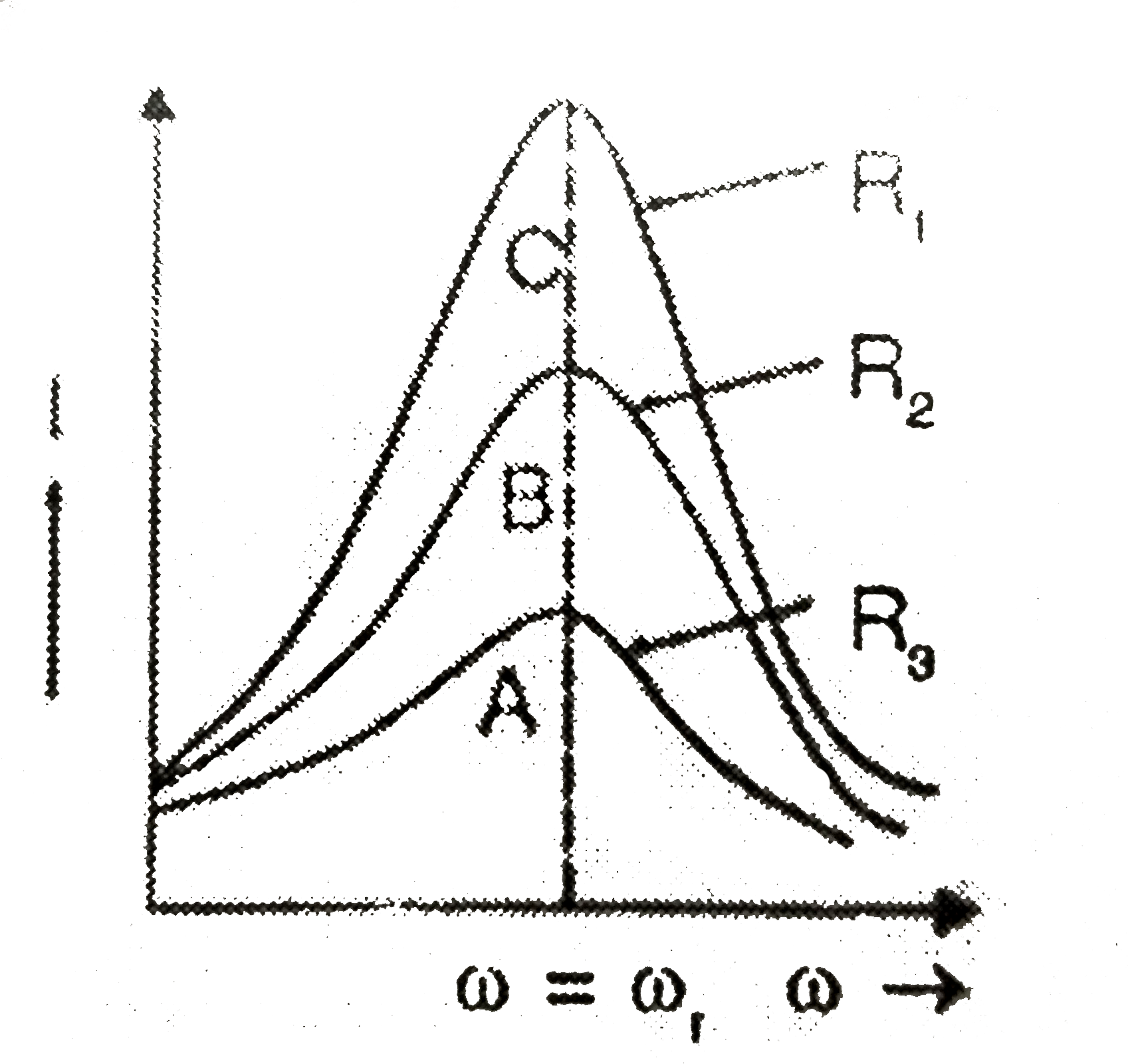
(a) What do you understand by 'sharpness of resonance' for a series LCR resonant circuit? How is it related with the quality factor 'Q' of the circuit? Using the graphs given in the diagram, explain the factors which affect it. For which graph is the resistance (R ) minimum?
(b) A 2μF capacitor, 100Ω resistor and 8H inductor are connected in series with an ac source. Find the frequency of the ac source for which the current drawn in the circuit is maximum.
If the peak value of emf of the source is 200 V, calculate the (i) maximum current, and (ii) inductive and capacitive reactance of the circuit at resonance.

View SolutionAn inductor (L=1100πH), a capacitor (C=1500πF) and a resistance (3Ω) is connected in series with an AC voltage source as shown in the figure. The voltage of the AC source is given as V=10cos(100πt) volt. What will be the potential difference between A and B ?

View Solution
