Consider the following circuit with a switch Sw. Potential difference of the cell is V. Initially, the switch is in position 1, connected to the left branch. After a long time the switch is shifted to position 2, to connect with the right branch.
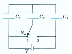
After the switch is shifted to position 2, find:
(a) charge flowing through the switch.
(b) work done by the battery.
(c) heat loss in redistribution of charge.
We can easily understand that in both the states of switch equivalent capacitance (C ) remains same, hence total stored charge (Q = CV) also remains same. In both the states parallel combination of C1 and C2 is connected in series with another capacitor C1 . We can write C and Q as follows:
C=C1(C1+C2)2C1+C2 ...(i)
Q=CV⇒Q=C1(C1+C2)V2C1+C2 ...(ii)
In the network C1andC2 are connected in parallel and total charge Q is divided between them, proportional to their capacitance. Hence, charge stored in C1andC2, connected in parallel, is Q1=QC1C1+C2andQ2=QC2C1+C2 respectively.
Distribution of charge in both the states of the circuit is shown in the figures.
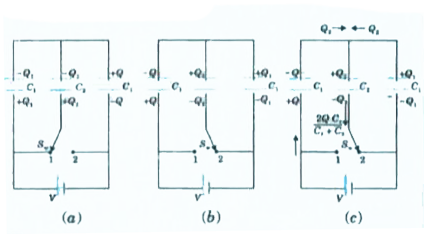
Fig-(a) shows charge distribution in state 1 of the circuit (when the switch is in position 1). Fig-(b) shows charge distribution in state 2 (when the switch is in positon 2) of the circuit. Fig-(c ) shows additional charge flowing through the various branches of circuit to adjust the charge distribution when the circuit changes its state.
(a) Lower plate of the middle capacitor has charge +QC2C1+C2 in the first state and in the second state the same plate has to acquire final charge −QC2C1+C2.
Hence, charge +2QC2C1+C2 will be released by this plate, which will flow through the switch as shown in Fig-(c ). On substituting value of Q from equation (ii) we get charge flowing through the switch as follows:
Charge through switch =+2C1(C1+C2)V2C1+2C2C2C1+C2=2C1C2V2C1+C2
(b) Lower plate of the left capacitor (C1) has a charge +QC1C1+C2 in the first state and the same plate has to acquire +Q charge in the second state of the circuit. Hence, charge +QC2C1+C2 must flow from positive terminal of the batery towards the lower plate of left capacitor. Hence, additional charge +QC2C1+C2 is supplied by the positive terminal battery when switch is shifted from position-1 to the positon-2.
Work done by the battery = (Charge supplied by the battery) × (potential difference of battery)
Wb=QC2C1+C2V=C1(C1+C2)V2C1+2C2C2C1+C2V=C1C2V22C1+C2
(c ) We already know that equivalent capacitance in both the states of the circuit is same and that potential difference applied is also the same. Hence, energy stored in the circuit has to be the same in both states.
U1=U2
According to energy conservation:
U1+Wb=U2+H
⇒H=Wb=C1C2V22C1+C2
Topper's Solved these Questions
- ELECTROSTATIC POTENTIAL AND CAPACITANCE BOOK - MODERN PUBLICATIONCHAPTER - ELECTROSTATIC POTENTIAL AND CAPACITANCE EXERCISE - NCERT FILE Solved (Textbook Exercise)
11 Videos
- ELECTROSTATIC POTENTIAL AND CAPACITANCE BOOK - MODERN PUBLICATIONCHAPTER - ELECTROSTATIC POTENTIAL AND CAPACITANCE EXERCISE - NCERT FILE Solved (Additional Exercises)
23 Videos
- ELECTROSTATIC POTENTIAL AND CAPACITANCE BOOK - MODERN PUBLICATIONCHAPTER - ELECTROSTATIC POTENTIAL AND CAPACITANCE EXERCISE - Conceptual Questions
37 Videos
- ELECTROMAGNETIC WAVESBOOK - MODERN PUBLICATIONCHAPTER - ELECTROMAGNETIC WAVESEXERCISE - CHAPTER PRACTICE TEST
14 Videos
- MAGNETISM AND MATTERBOOK - MODERN PUBLICATIONCHAPTER - MAGNETISM AND MATTEREXERCISE - CHAPTER PRACTICE TEST FOR BOARD EXAMINATION
16 Videos
Similar Questions
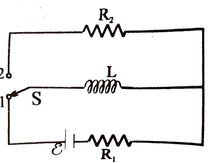
In the circuit shown, initially the switch is in position 1 for a long time. Then the switch is shifted to position 2 for a long time. Find the total heat produced in R2
View SolutionInitially, switch S is connected to position 1 for a long time . The net amount of heat generated in the circuit after it is shifted to position 2 is .
View Solution
Knowledge Check
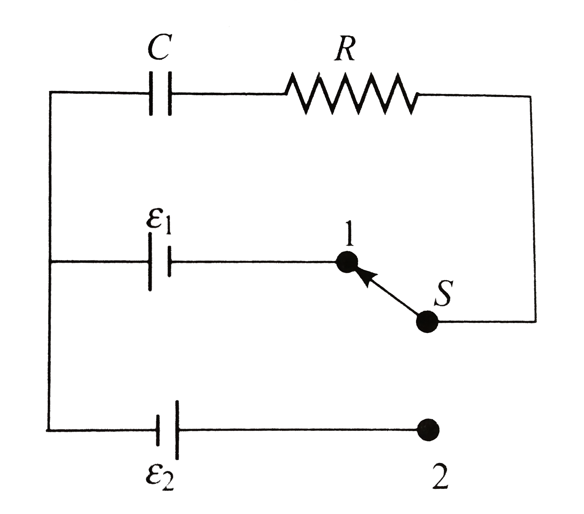
Initially, switch S is connected to position 1 for a long time . The net amount of heat generated in the circuit after it is shifted to position 2 is .
 AC2(ε1+ε2)ε2BC(ε1+ε2)ε2CC2(ε1+ε2)2DC(ε1+ε2)2
In the circuit shown below, the switch is in position 1 for a long time. At some moment after that the switch is thrown in position 2. The quantity of heat generated in the resistance of 375 ohm after the switch is changes to position 2 is :
 A0.15 JB0.25 JC0.50 JD0.10 J
In figure, the switch is in the position 1 for long time, then the switch is shifted to position 2 at t=0. At this instant the value of i1 and i2 are
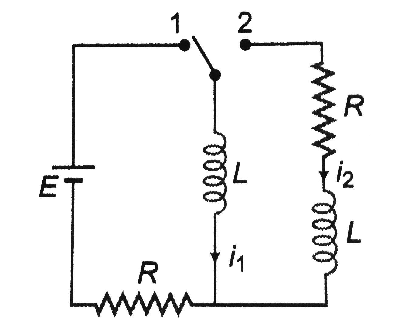 AER,0BER,−ERCE2R,−E2RDNone of these
In the circuit shown below, the switch is in position 1 for a long time. At some moment after that the switch is thrown in position 2. The quantity of heat generated in the resistance of 375 ohm after the switch is changes to position 2 is :

View SolutionIn figure, the switch is in the position 1 for long time, then the switch is shifted to position 2 at t=0. At this instant the value of i1 and i2 are

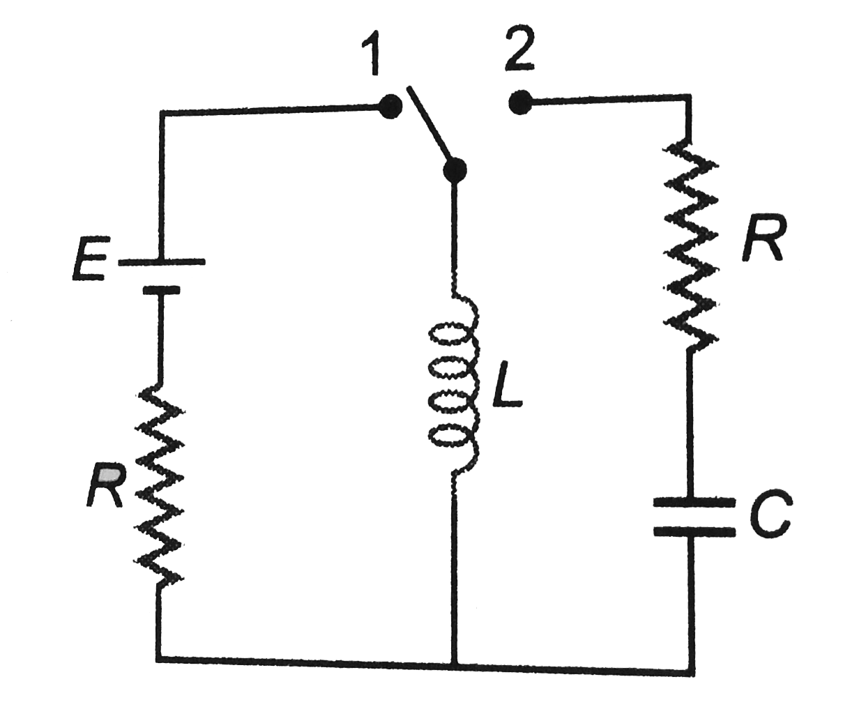
View SolutionInitially the switch is in positions 1 for as long time then shifted to position 2 at t=0 as shown in figure. Just after closing the switch, the magnitude of current through the capacitor is
View SolutionConsider the circuit shown in figure, after switch S is closed.
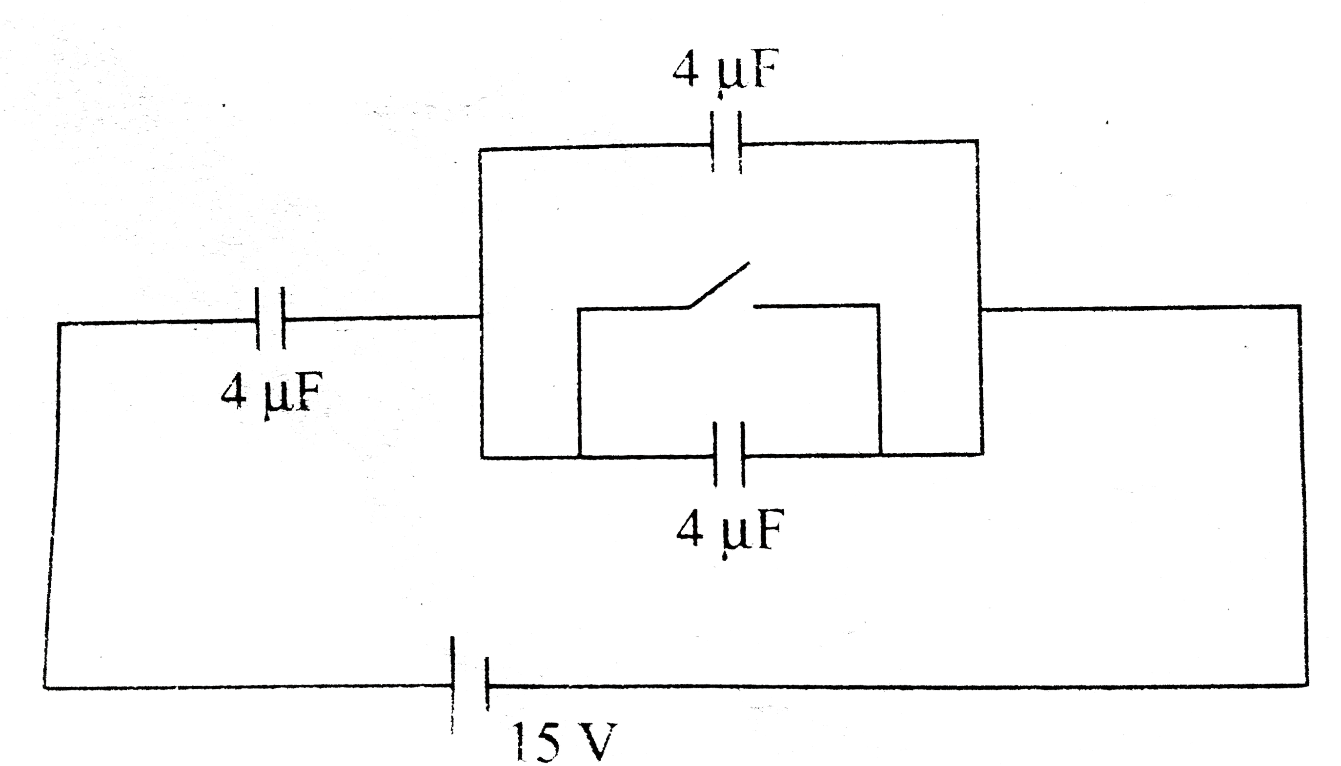
What amount of charge will flow through the switch?
View SolutionInitially the switch is in positions 1 for as long time then shifted to position 2 at t=0 as shown in figure. Just after closing the switch, the magnitude of current through the capacitor is

View Solution
