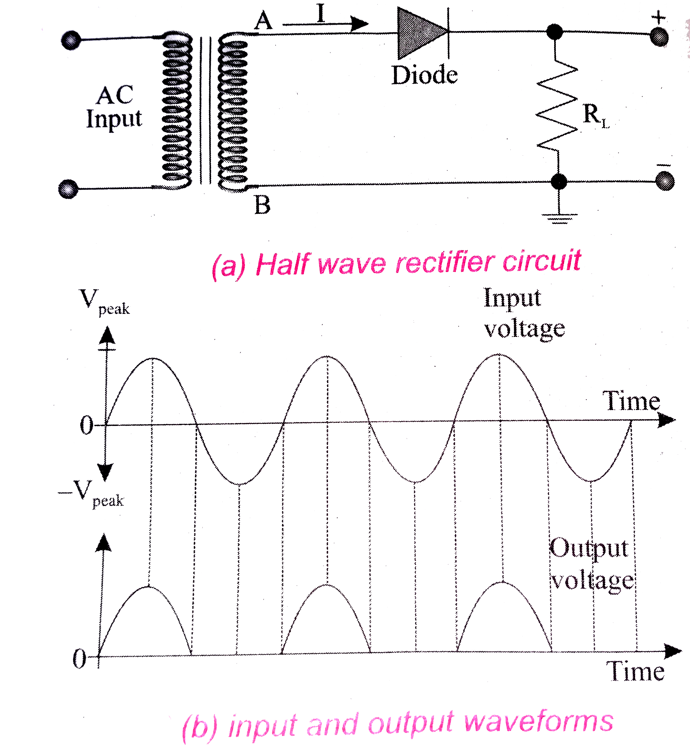
Draw the circuit diagram of a half wave rectifier and explain its working .
Rectification is the process of converting alternating current into direct current is called rectification .
In hafl wave rectifier circuit , either a positive half of the negative half of the AC input is passed through while the other half is blocked . Only one half of the input wave reaches the output . A p-n junction can be used as half wave rectifier .

When the positive half cycle of the AC input signal passes through the circuit , therminal A become positive with respect to terminal B. The diode is forward biased and hence it conducts . The current flows thorugh the load resistance and AC voltage developed across constitues the output voltage and the wavelength of the diode is shown in the fig (b)
When the negative half cycle of the AC input signal passes through the circuit , teminal a is negative with respect to terminal B . Now the diode is reverse biased and does not conduct and hence no current passes through . The reverse saturation current in a diode is negligible. Since there is no voltage drop across , the negative half cycle of AC supply is suppressed at the output . The output of the half wave rectifier is not a steady DC voltage but a pulsating wave . The efficient of half wave rectifier is 40.6% .
Similar Questions
Draw the circuit diagram of a half wave rectifier. Hence explain its working.
View SolutionDraw the circuit diagram of a full wave rectifier. Explain its working showing its input and output waveforms.
View SolutionDraw a circuit diagram of a full-wave rectifier. Explain its working principle. Draw the input/output wave forms indicating clearly the function of the two diode used.
View SolutionDraw a circuit diagram of a full-wave rectifier. Explain its working principle. Draw the input/output wave forms indicating clearly the function of the two diode used.
View SolutionDraw a circuit diagram of a full-wave rectifier. Explain its working principle. Draw the input/output wave forms indicating clearly the function of the two diode used.
View SolutionDraw a labelled circuit diagram of a half wave rectifier and give its output waveform.
View SolutionDraw the circuit diagram of a half - wave rectifier using a p-n junction diode.
View SolutionDraw the circuit diagram of transistor as an oscillator and explain its working.
View SolutionDraw the circuit diagram of half wave rectifier, showing input and output voltages.
View SolutionDrawa labelled diagram of a full-wave rectifier circuit and briefly explain its working, Show the input-output waveforms.
Or
A student wants to use two p-n junction diodes to convert a.c. into d.c. Draw the labelled circuit diagram she would use and explain how it works.
View Solution
