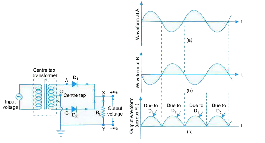
Draw the circuit diagram of a full wave rectifier. Explain its working showing its input and output waveforms.
The circuit arrangement of a full-wave rectifier using two diodes D1, and D2, has been drawn here. We use a centre tap transformer having its secondary wound into two equal parts such that voltages at any instant at A (input of diode D1,) and B (input of diode D2,) are out of phase with each other. Let initially input voltage at A is positive then it will be negative voltage at B at that instant. Consequently diode D1, being in forward bias, conducts while D2, being in reverse bias, does not conduct. We get output current and hence output voltage across load resistance R, joined between X and Y due to D1. Aler hall-cycle of a.c. input, voltage at A becomes negalive and that at B positive. Now diode D1 does not conduct but D2 conducts and output voltage is again obtained across RL in the same direction. Thus, output is obtained throughout the input wave cycle. The input and output waveforms have been shown in the figure.

Topper's Solved these Questions
- CBSE EXAMINATION PAPER 2020 (SOLVED)BOOK - U-LIKE SERIESCHAPTER - CBSE EXAMINATION PAPER 2020 (SOLVED)EXERCISE - SECTION D
11 Videos
- CBSE EXAMINATION PAPER 2020 (SOLVED)BOOK - U-LIKE SERIESCHAPTER - CBSE EXAMINATION PAPER 2020 (SOLVED)EXERCISE - SECTION B
10 Videos
- CBSE EXAMINATION PAPER 2020 BOOK - U-LIKE SERIESCHAPTER - CBSE EXAMINATION PAPER 2020 EXERCISE - SECTION D
12 Videos
- CBSE EXAMINATION PAPER 2020 (SOLVED) BOOK - U-LIKE SERIESCHAPTER - CBSE EXAMINATION PAPER 2020 (SOLVED) EXERCISE - SECTION - D
6 Videos
Similar Questions
Draw the circuit diagram of a half wave rectifier. Hence explain its working.
View SolutionDraw a circuit diagram of a full-wave rectifier. Explain its working principle. Draw the input/output wave forms indicating clearly the function of the two diode used.
View SolutionDraw a circuit diagram of a full-wave rectifier. Explain its working principle. Draw the input/output wave forms indicating clearly the function of the two diode used.
View SolutionDraw a circuit diagram of a full-wave rectifier. Explain its working principle. Draw the input/output wave forms indicating clearly the function of the two diode used.
View Solution(a) Draw the circuit diagram of a full wave rectifier using p-n junction diole. Explain its working and show the output, input waveforms.
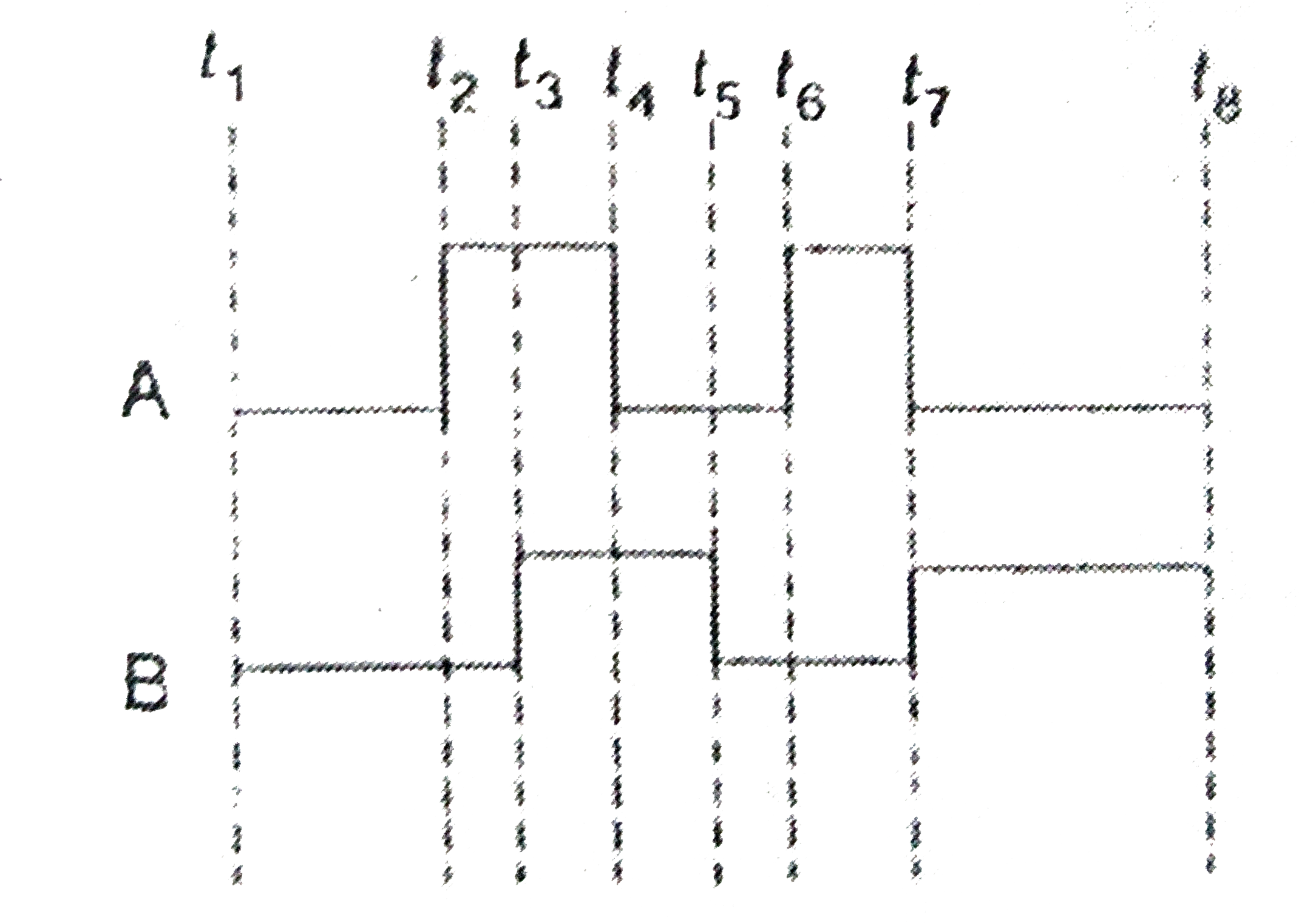
(b) Show the output waveforms (Y) for the following inputs A and B of (i) OR gate (ii) NAND gate :

View SolutionDraw circuit diagram for a full wave rectifier and show input output voltages.
View SolutionDrawa labelled diagram of a full-wave rectifier circuit and briefly explain its working, Show the input-output waveforms.
Or
A student wants to use two p-n junction diodes to convert a.c. into d.c. Draw the labelled circuit diagram she would use and explain how it works.
View SolutionDraw the circuit diagram of half wave rectifier, showing input and output voltages.
View SolutionDraw a labelled circuit diagram of a half wave rectifier and give its output waveform.
View SolutionWith the help of a labelled circuit diagram, explain how a junction diode is used as a full- wave rectifier. Draw its input and output wave formns. How do you obtain steady d.c. output from the pulsating voltage ?
View Solution
