Draw a circuit diagram of a full-wave rectifier. Explain its working principle. Draw the input/output wave forms indicating clearly the function of the two diode used.
Step-by-Step Solution
Step 1: Draw the Circuit Diagram of a Full-Wave Rectifier
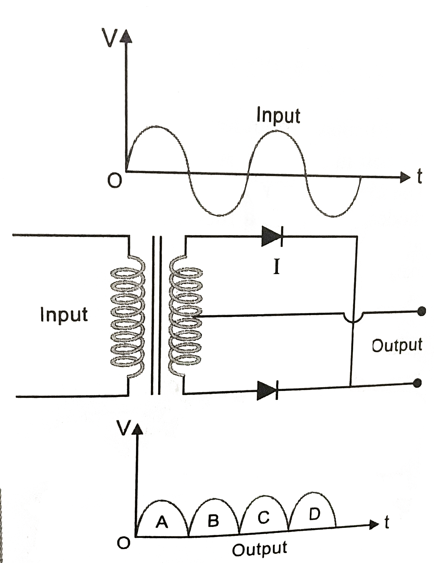
To draw the circuit diagram of a full-wave rectifier, we will use two diodes, a transformer, and a load resistor. The transformer steps down or steps up the AC voltage, and the diodes rectify the AC voltage into pulsating DC.
1. Transformer: Draw a transformer with primary and secondary coils. Label the primary side as A and B, and the secondary side as C and D.
2. Diodes: Connect two diodes (D1 and D2) to the secondary coil.
- Connect D1 with its anode to C and cathode to the load resistor.
- Connect D2 with its anode to D and cathode to the load resistor.
3. Load Resistor: Connect a load resistor (RL) across the cathodes of both diodes.
4. Input AC Source: Indicate the AC input source connected to the primary side of the transformer.
Circuit Diagram:
ACSource||AB||||(Tranormer)||CDD1D2 −−−−(LoadResis→rRL)
---
Step 2: Explain the Working Principle
1. Positive Half Cycle:
- During the positive half cycle of the AC input, terminal A is positive and terminal B is negative.
- This causes diode D1 (connected to C) to become forward-biased and conduct current, while diode D2 (connected to D) becomes reverse-biased and does not conduct.
- The current flows through D1 and the load resistor (RL), producing a positive output.
2. Negative Half Cycle:
- During the negative half cycle, terminal A becomes negative and terminal B becomes positive.
- This causes diode D2 to become forward-biased and conduct, while diode D1 becomes reverse-biased and does not conduct.
- The current flows through D2 and the load resistor (RL), again producing a positive output.
3. Output Waveform:
- The output is a pulsating DC waveform, which consists of both halves of the AC input being utilized, resulting in a smoother DC output compared to a half-wave rectifier.
---
Step 3: Draw Input and Output Waveforms
1. Input Waveform: Draw a sinusoidal waveform representing the AC input voltage. Label the positive and negative half cycles.
2. Output Waveform: Draw a pulsating DC waveform that reflects the output from the full-wave rectifier. The output waveform should show positive peaks corresponding to both the positive and negative half cycles of the input.
Waveforms:
InputWaveform:++++| | | || | | || | | |−−⊢−−−−−−⊢−−−−−−⊢−−−−−−⊢−−−−−−Time| | | || | | || | | |−−−−<p><p>OutputWaveform:++++| | | || | | |−−⊢−−−−−−⊢−−−−−−⊢−−−−−−⊢−−−−−−Time| | | || | | |−−−−
---
2. Diodes: Connect two diodes (D1 and D2) to the secondary coil.
- Connect D1 with its anode to C and cathode to the load resistor.
- Connect D2 with its anode to D and cathode to the load resistor.
3. Load Resistor: Connect a load resistor (RL) across the cathodes of both diodes.
4. Input AC Source: Indicate the AC input source connected to the primary side of the transformer.
ACSource||AB||||(Tranormer)||CDD1D2 −−−−(LoadResis→rRL)
- During the positive half cycle of the AC input, terminal A is positive and terminal B is negative.
- This causes diode D1 (connected to C) to become forward-biased and conduct current, while diode D2 (connected to D) becomes reverse-biased and does not conduct.
- The current flows through D1 and the load resistor (RL), producing a positive output.
- During the negative half cycle, terminal A becomes negative and terminal B becomes positive.
- This causes diode D2 to become forward-biased and conduct, while diode D1 becomes reverse-biased and does not conduct.
- The current flows through D2 and the load resistor (RL), again producing a positive output.
- The output is a pulsating DC waveform, which consists of both halves of the AC input being utilized, resulting in a smoother DC output compared to a half-wave rectifier.
2. Output Waveform: Draw a pulsating DC waveform that reflects the output from the full-wave rectifier. The output waveform should show positive peaks corresponding to both the positive and negative half cycles of the input.
InputWaveform:++++| | | || | | || | | |−−⊢−−−−−−⊢−−−−−−⊢−−−−−−⊢−−−−−−Time| | | || | | || | | |−−−−<p><p>OutputWaveform:++++| | | || | | |−−⊢−−−−−−⊢−−−−−−⊢−−−−−−⊢−−−−−−Time| | | || | | |−−−−
Topper's Solved these Questions
- BOOK - XII BOARD PREVIOUS YEAR PAPER ENGLISHCHAPTER - XII BOARDSEXERCISE - PHYSICS (Theory) DELHI BOARD -2016 [SET -I][COMPTT.]11videos
XII BOARDS
- BOOK - XII BOARD PREVIOUS YEAR PAPER ENGLISHCHAPTER - XII BOARDSEXERCISE - C.B.S.E.CLASS-XII PHYSICS (THEORY) [SET-I] (SECTION-A)5videos
XII BOARDS
- BOOK - XII BOARD PREVIOUS YEAR PAPER ENGLISHCHAPTER - XII BOARDSEXERCISE - SECTION-B52videos
XII BOARDS
- BOOK - XII BOARD PREVIOUS YEAR PAPER ENGLISHCHAPTER - SAMPLE PAPER 2019EXERCISE - SECTION D6videos
SAMPLE PAPER 2019
Similar Questions
Draw the circuit diagram of a half - wave rectifier using a p-n junction diode.
View SolutionDraw a neatly labelled circuit diagram of a full wave rectifier using two junction diodes.
View SolutionWhat is the output form of full-wave rectifier ?
View SolutionDraw a simple diagram of a hydraulic jack and explain its working.
View SolutionDraw a labelled circuit diagram of a half wave rectifier and give its output waveform.
View Solution(a) Draw the circuit diagram of a full wave rectifier using p-n junction diole. Explain its working and show the output, input waveforms.
(b) Show the output waveforms (Y) for the following inputs A and B of (i) OR gate (ii) NAND gate :
 View Solution
Draw a schematic diagram of a cyclotron. Explain its underlying principle and working, stating clearly the function of the electric and magnetic fields applied on a charged particle.
Deduce an expression for the period of revolution and show that it does not depend on the speed of the charged particle.View SolutionDraw a schematic diagram of a step-up transformer . Explain its working principle . Deduce the expression for the secondary to primary voltage in terms of the number of turns in the two coils . In an ideal transformer , how is this ratio related to the currents in the two coils ?
View SolutionA full wave rectifier circuit along with the input and output are shown in Fig. the concentrations from the diode I is (are)
 View Solution
A full wave rectifier circuit along with the input and output are shown in the figure. The contribution from the diode D2 is (are)
View Solution

