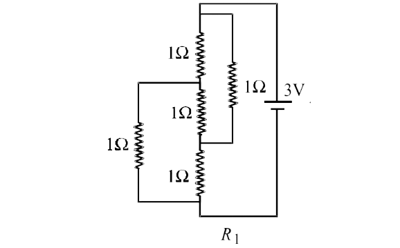
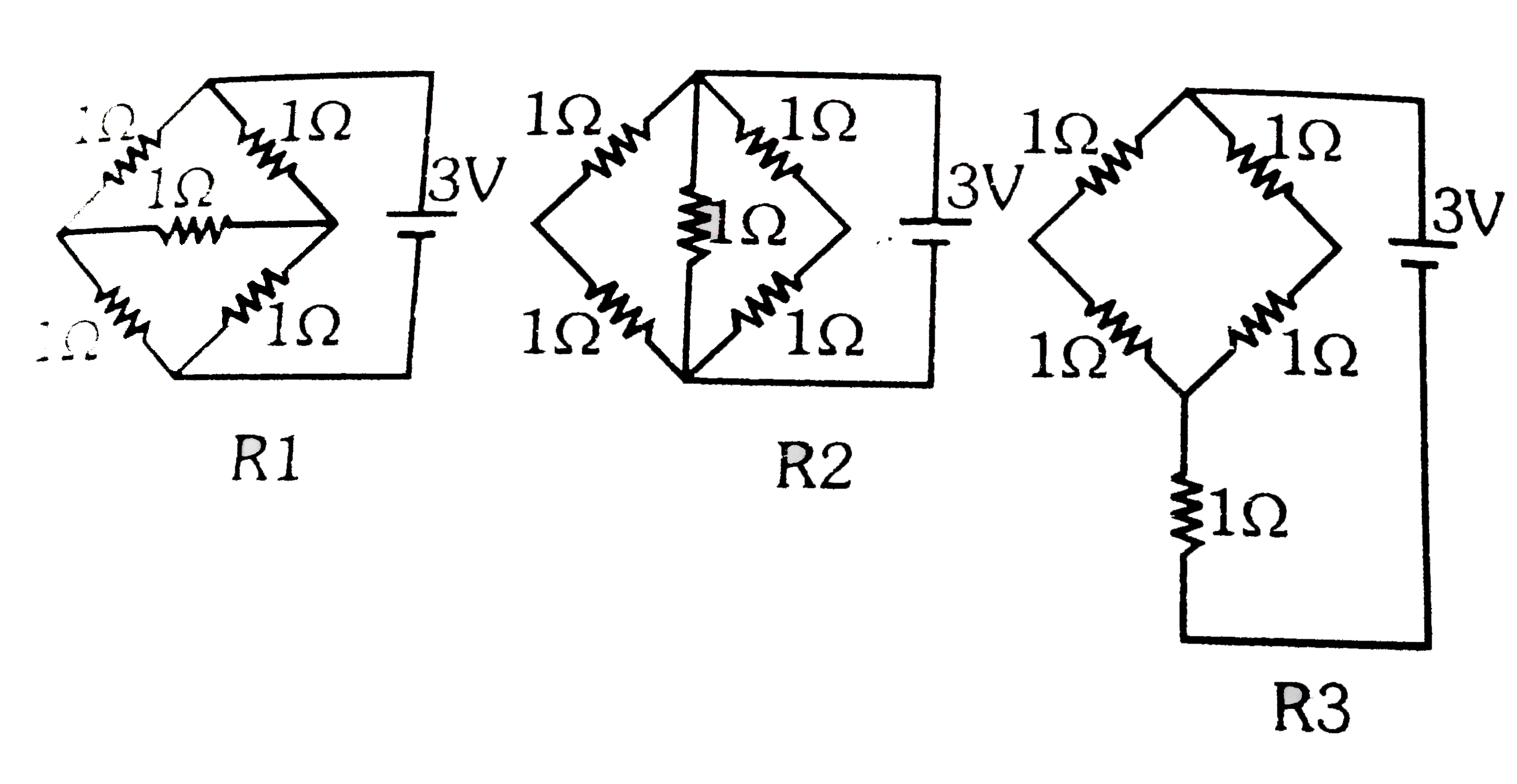
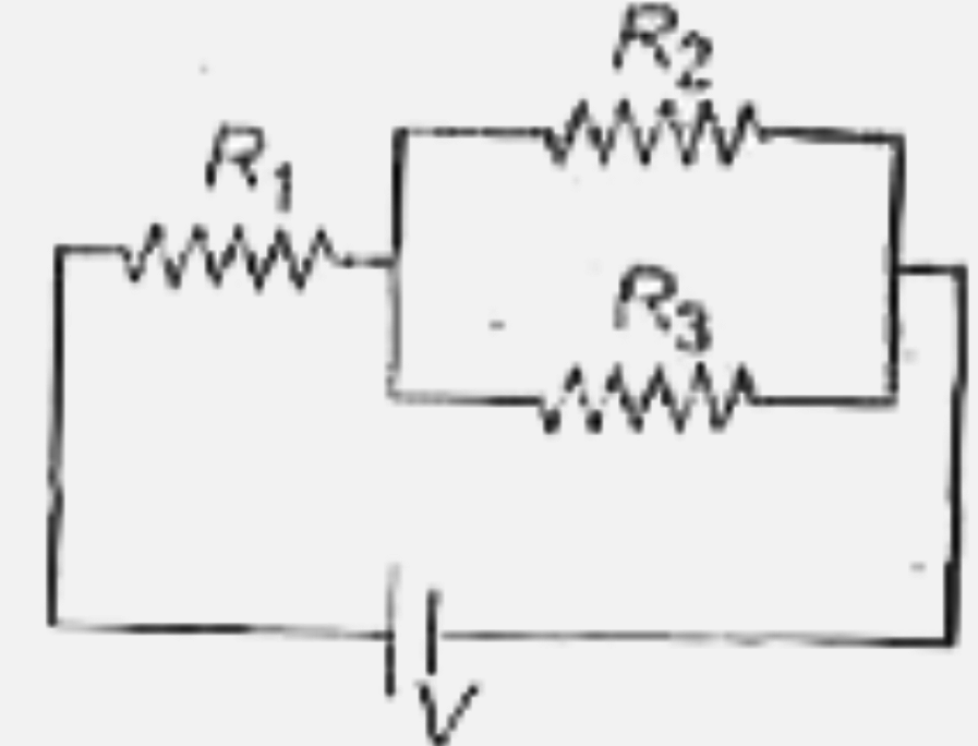
Figure shows three resistor configurations R1,R2andR3 connected to 3V battery. If the power dissipated by the configuration R1,R2andR3 is P1,P2andP3, respectively. Then -
P1<P2<P3
P1>P2>P3
P2>P1>P3
P3>P2>P1
The correct Answer is:C
c. Here, R1=1Ω,R2=1/2Ω,R3=3Ω
As P=V2R,soP2>P1>P3.
Similar Questions
Figure shows three resistor configurations R1,R2 and R3 connected to 3 V battery .
If the powers dissipated by the configuration R1,R2 and R3 are P1,P2 and P3, respectively, thenView SolutionFigure shows three resistor configurations R1,R2 and R3 connected to 3 V battery .

If the powers dissipated by the configuration R1,R2 and R3 are P1,P2 and P3, respectively, thenView SolutionFigure shows three resistor configurations R1,R2 and R3 connected to 3 V battery .

If the powers dissipated by the configuration R1,R2 and R3 are P1,P2 and P3, respectively, thenView SolutionFig shows three resistor configuration R1,R2andR3 connected to 3V battery. If the power dissipated by the configuration R1,R2andR3 is P1,P2andP3 respectively, then
 View Solution
A resistor of resistance R is connected to an ideal battery. If the value of R is decreased,the power dissipated in the resistor will
View SolutionA resistor of resistance R is connected to an ideal battery. If the value of R is decreased,the power dissipated in the resistor will
View SolutionThree identical resistors R1=R2=R3 are connected as shown to a battery of constant e.m.f . The power dissipated is
 View Solution
Three resistors R1,R2 and R3 are to be combined to form an electrical circuit as shown in the figure. It is found that when R1R2andR3 are put respectively in positions A, B and C, the effective resistance of the circuit is 70 ΩWhen R2,R3andR1 are put respectively in position A, B and C the effective resistance is 35Ω and when R3,R1andR2 are respectively put in the position A, B and C, the effective resistance is 42Ω
If R1,R2andR3 are all connected in parallel, the effective resistance will beView SolutionThree resistors R1,R2 and R3 are to be combined to form an electrical circuit as shown in the figure. It is found that when R1R2andR3 are put respectively in positions A, B and C, the effective resistance of the circuit is 70 ΩWhen R2,R3andR1 are put respectively in position A, B and C the effective resistance is 35Ω and when R3,R1andR2 are respectively put in the position A, B and C, the effective resistance is 42Ω
If R1,R2 andR3are put in series, the effective resistance will beView SolutionThree resistors R1,R2 and R3 are to be combined to form an electrical circuit as shown in the figure. It is found that when R1R2andR3 are put respectively in positions A, B and C, the effective resistance of the circuit is 70 ΩWhen R2,R3andR1 are put respectively in position A, B and C the effective resistance is 35Ω and when R3,R1andR2 are respectively put in the position A, B and C, the effective resistance is 42Ω
The resistanceR1:R2:R3are in the ratioView Solution

