Find the output of the ideal operational amplifier shown in the figure for each of the following input signals
VIn=−2.5Vdc

The gain of the amplifier Av=−RfRIn=−39×10315×103
=−2.6
V0=2.6×(−2.5V)+6.5Vd.c
Topper's Solved these Questions
- SEMI-CONDUCTORS ELECTRONICSBOOK - OSWAAL PUBLICATIONCHAPTER - SEMI-CONDUCTORS ELECTRONICSEXERCISE - TOPIC -4 LOGIC GATES (VERY SHORT ANSWER TYPE QUESTIONS)
3 Videos
- SEMI-CONDUCTORS ELECTRONICSBOOK - OSWAAL PUBLICATIONCHAPTER - SEMI-CONDUCTORS ELECTRONICSEXERCISE - TOPIC -4 LOGIC GATES (SHORT ANSWER TYPE QUESTIONS-I)
14 Videos
- SEMI-CONDUCTORS ELECTRONICSBOOK - OSWAAL PUBLICATIONCHAPTER - SEMI-CONDUCTORS ELECTRONICSEXERCISE - TOPIC -3 TRANSISTORS AND THEIR APPLICATIONS (LONG ANSWER TYPE QUESTIONS-)
10 Videos
- Sample Paper 8BOOK - OSWAAL PUBLICATIONCHAPTER - Sample Paper 8EXERCISE - Exercise
37 Videos
- SOLVED PAPER (II PUC JULY 2016)BOOK - OSWAAL PUBLICATIONCHAPTER - SOLVED PAPER (II PUC JULY 2016)EXERCISE - PART D
11 Videos
Similar Questions
If in p-n junction diode a sinusoidal input signal is applied as shown Then the output signal across RL will bw
View SolutionInput signal A and B are applied to the input terminals of the 'dotted box' set up shown here. Ley y be the final output signal from the box. What are the wavefroms of the signal labelled as C1 and C2 within the box giving (in brief) the reasons for getting these wave forms. Hence draw the waveform of the final output signal y. Give reasons for your choice. Write the relation between the total output y and the input signals A and B?
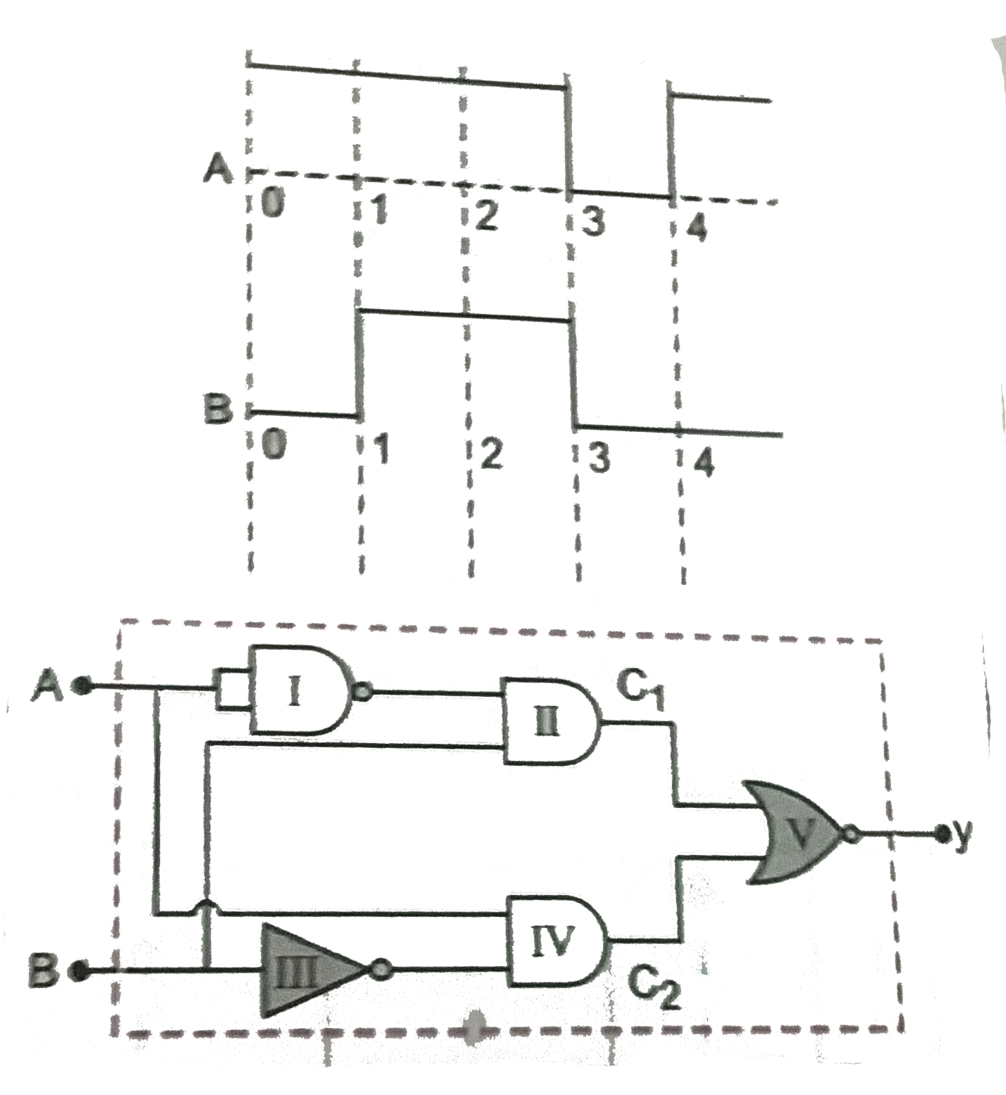
View Solution
Knowledge Check
An input voltage Vi of 0.20V is applied to an operational amplifier connected as shown in the diagram. What is the output voltage V0?
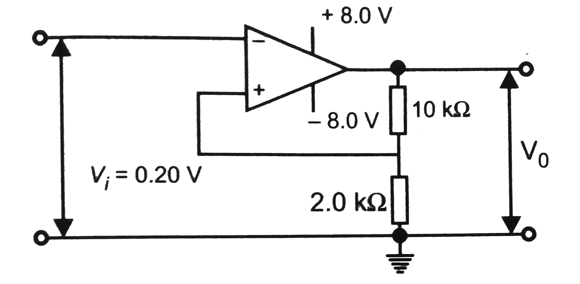 A0.20VB1.2VC0.80VD8.0V
The figure below shows a circuit and its input voltage vi as function of time t.
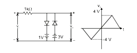
Assuming the diodes to be ideal, which of the following graphs depicts the output voltage v0 as function of time t ?A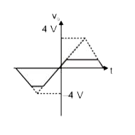 B
B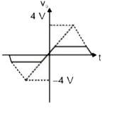 C
C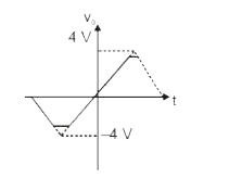 D
D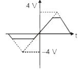

In p-n junction diode a square input signal of 10 V is applied as shown in figure The output signal across RL will beA B
B C
C D
D
Two amplifiers are connected one after the other in series. The first amplifier has a voltage gain of 10 and the second has a voltage gain of 20. If the input signal is 0.012 volt then output signal (in V)?
View SolutionA common emitter circuit is used as an amplifier. Its current gain is 50 . If the input resistance is 1kohm and the input voltage is 5V, then the output current (in mA) will be
View SolutionDraw the circuit diagram of a common emitter amplifier using n-p-n transistor. What is the phase difference between the input signal and output voltage? State two reasons why a common emitter amplifier is preferred to a common base amplifier.
View SolutionIf a p−n junction diode, a square input signal of 10V is applied as shown.
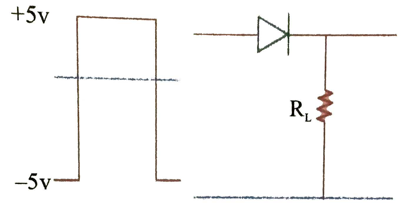
Then the out put signal across RL will be
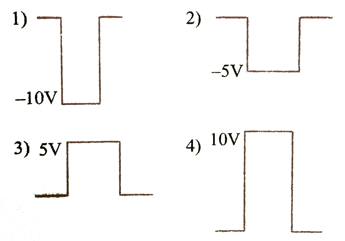 .
.
View Solution
In p-n junction diode a square input signal of 10 V is applied as shown in figure The output signal across RL will be
View Solution
