For given circuit the input digital signals are applied at terminal A,B, C. What would be output at terminals? 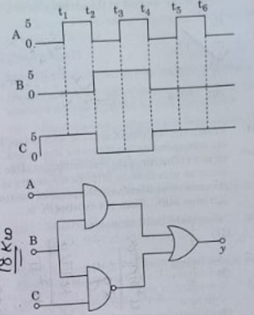


Step by step video & image solution for For given circuit the input digital signals are applied at terminal A,B, C. What would be output at terminals? by Physics experts to help you in doubts & scoring excellent marks in Class 12 exams.
Updated on:21/07/2023Topper's Solved these Questions
Similar Questions
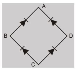
For the given circuit shown in fig, to act as full wave rectifier :– a.c. input should be connected across ................. and ..................... the d.c. output would appear across ................ and .....................
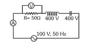
View SolutionIn given LCR circuit, the voltage across the terminals of a resistance & current will be–
View Solution
Knowledge Check
In the diagram, the input is across the terminals A and C and the output is across the terminals B and D, then the outputs is
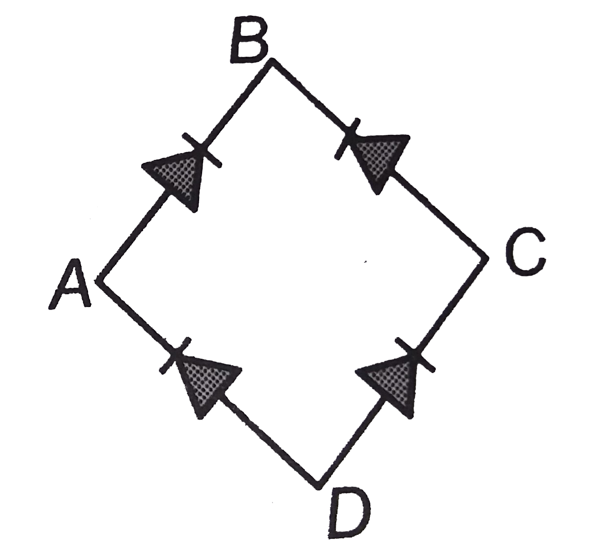 AzeroBsame as inputCFull wave rectifierDHalf wave rectifier
The gate that has only one input terminal
ANOTBNORCNANDDXORIn a common emitter amplifier the input signal is applied across
AAny whereBEmitter-collectorCCollector-baseDBase - emitter
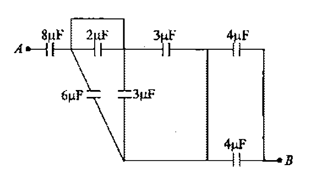
In the circuit shown in figure find the equivalent capacitance between terminals A and B.
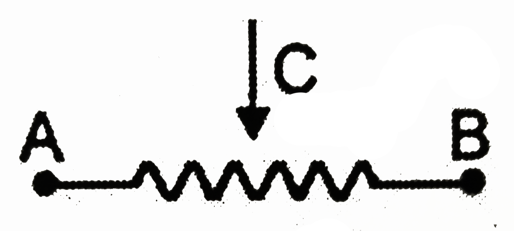
View SolutionConnect a battery to the terminals and completer the circuit diagram fo that it works as a potential divider meter. Indicate the output terminals also.
View Solution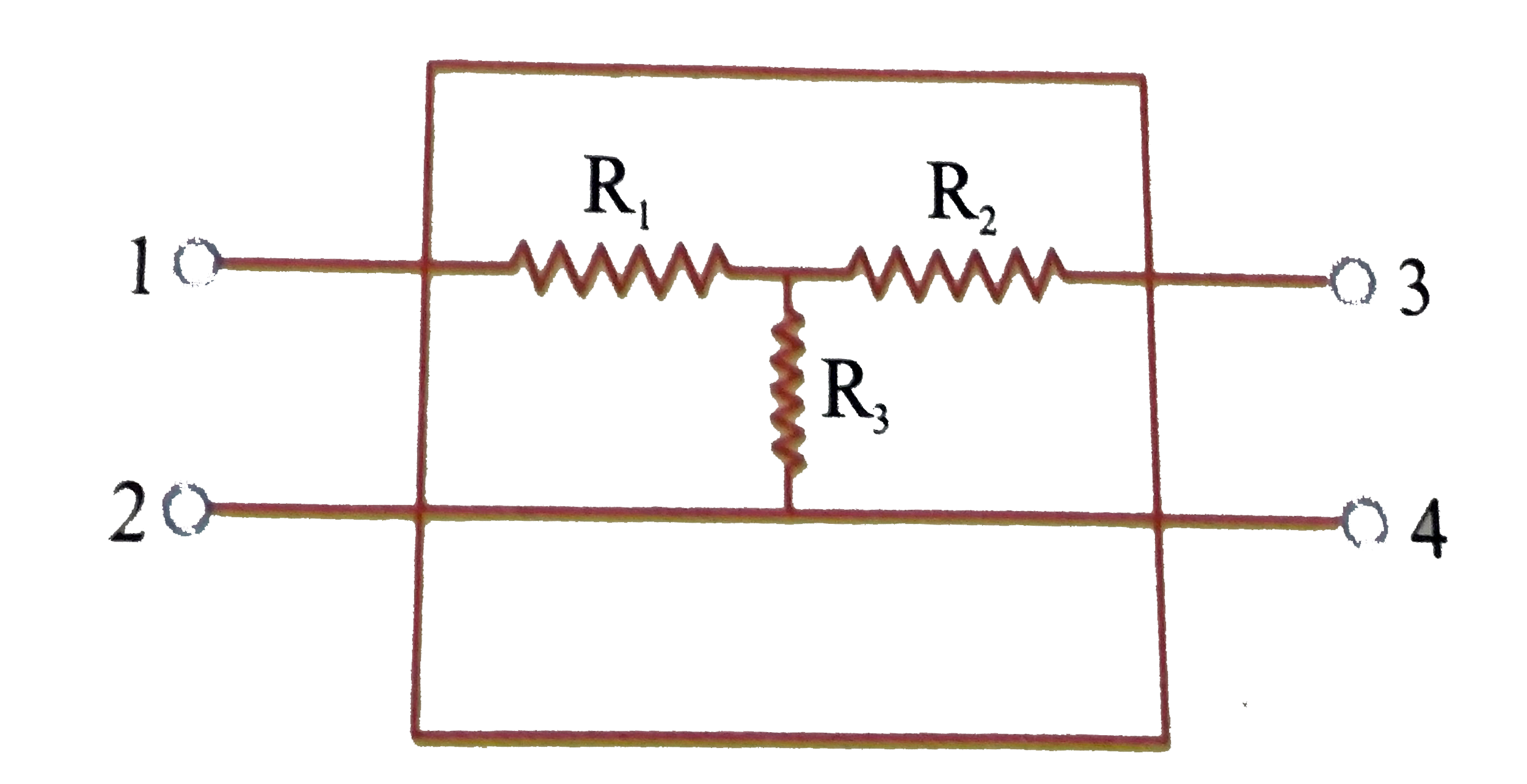
If voltage is applied between terminals 1 and 2 when terminals 3 and 4 are open the power liberated is P1=40W and when terminals 3 and 4 are connected, the power liberated is P2=80W. If the same source is connected to the terminals 3 and 4, the power liberated in the circuit when terminals 1 and 2 are open in P3=20W. Determine the power P4 consumed in the circuit when the terminals 1 and 2 are connected and the same voltage is applied between the terminals 3 and 4.
View SolutionIn Fig. the input is across the terminals A and C and the output is across B and D. Then the output is
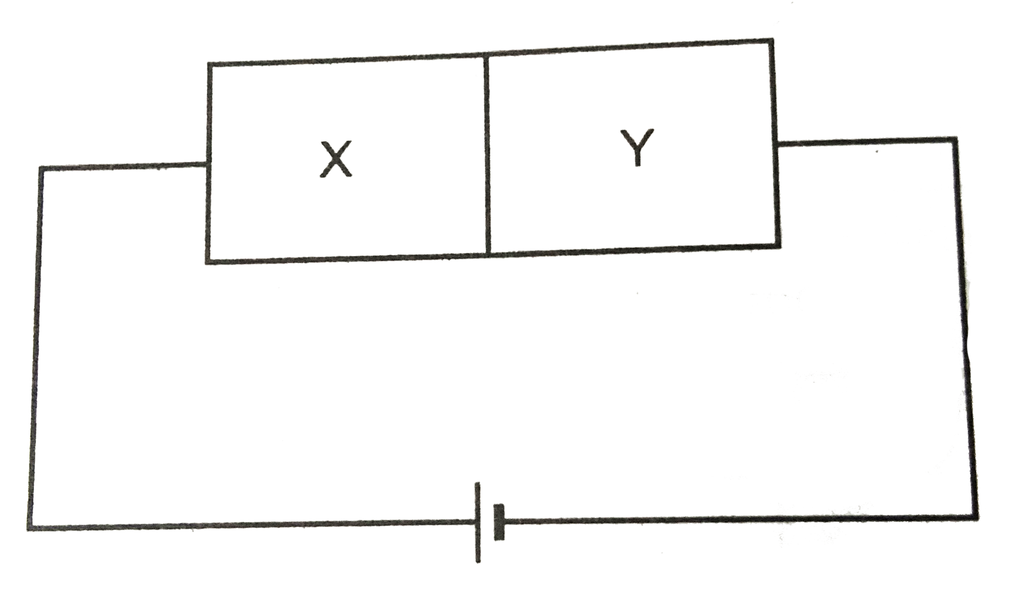
View SolutionIn the given circuit P and Q from the inputs. The output Y is
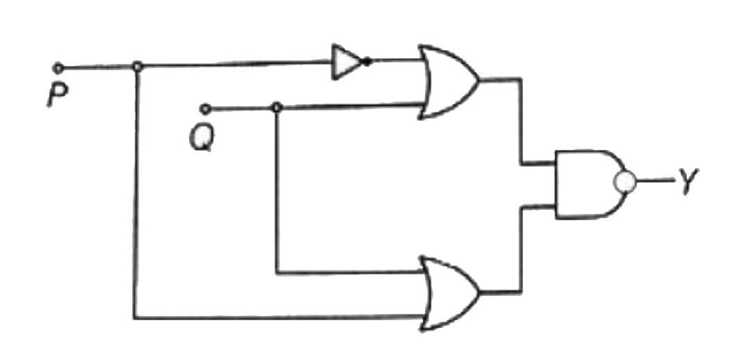
View Solution
