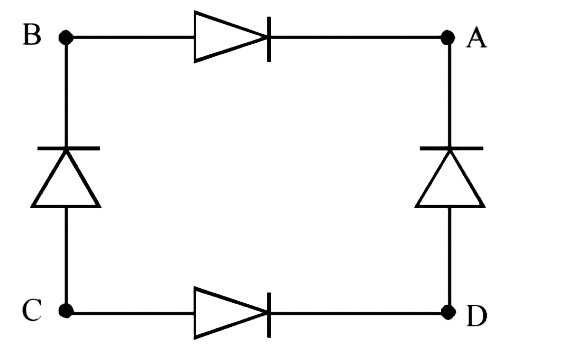
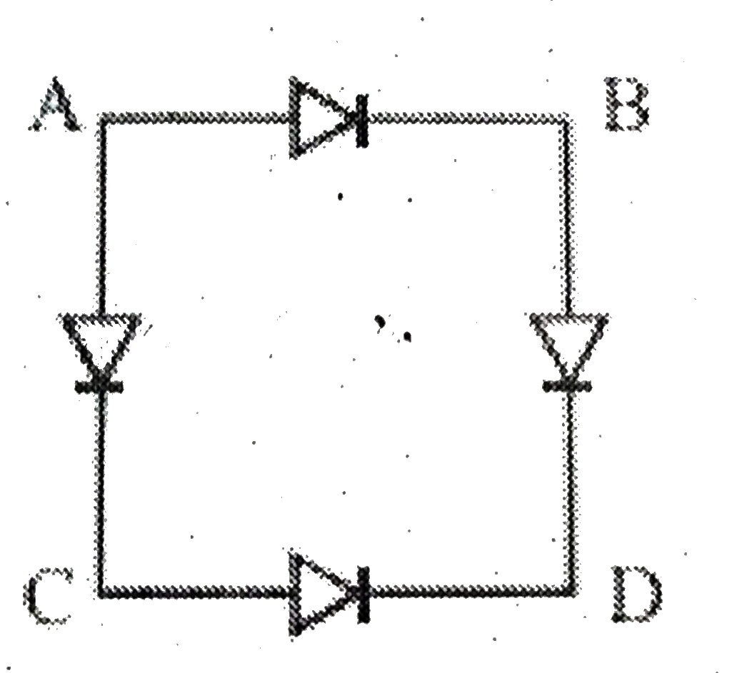
For the given circuit shown in fig, to act as full wave rectifier :– a.c. input should be connected across ................. and ..................... the d.c. output would appear across ................ and .....................
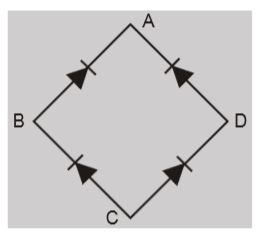
A, C, B, D
B, D, A, C
A, B, C, D
C, A, D, B
The correct Answer is:B
Step by step video & image solution for For the given circuit shown in fig, to act as full wave rectifier :– a.c. input should be connected across ................. and ..................... the d.c. output would appear across ................ and ..................... by Physics experts to help you in doubts & scoring excellent marks in Class 12 exams.
Updated on:21/07/2023Topper's Solved these Questions
- ELECTRONICS - SEMI CONDUCTORBook:MOTIONChapter:ELECTRONICS - SEMI CONDUCTORExercise:EXERCISE - 2
Explore 32 Videos
- ELECTRONICS - SEMI CONDUCTORBook:MOTIONChapter:ELECTRONICS - SEMI CONDUCTORExercise:EXERCISE - 3
Explore 29 Videos
- ELECTRONICS - SEMI CONDUCTORBook:MOTIONChapter:ELECTRONICS - SEMI CONDUCTORExercise:ADVANTAGES OF SEMICONDUCTOR DEVICES OVER VACCUM TUBES
Explore 3 Videos
- ELECTROMAGNETISMBook:MOTIONChapter:ELECTROMAGNETISMExercise:Exercise
Explore 136 Videos
- ELECTROSTATICSBook:MOTIONChapter:ELECTROSTATICSExercise:Exercise -3 Section (B) Previous Year Problems | JEE Main
Explore 30 Videos
Similar Questions
Knowledge Check
When an a.c source is connected across a resistor
AThe current leads the voltage in phaseBThe current lags behind the voltage in phaseCThe current and voltage are in same phaseDThe current and voltage are out of phaseIf Input frequency of a full wave rectifier be n, then output frequency would be
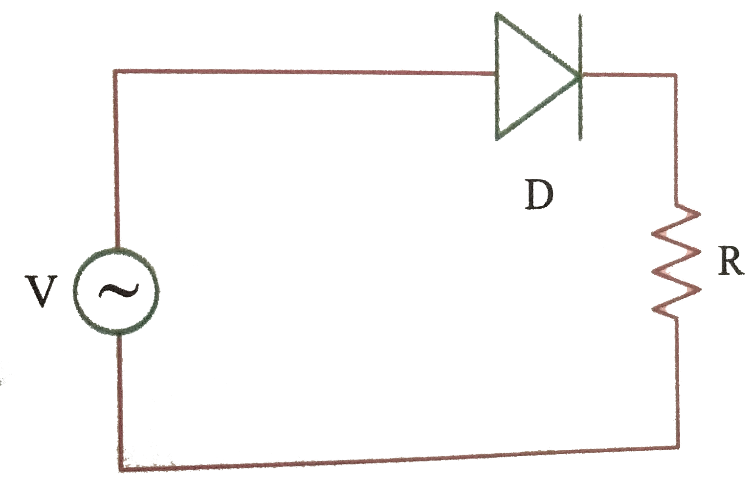
An2BnC3n2D2nA p−n junction (D) shown in the figure can act as a rectifier. An alternating current source (V) is connected in the circuit.
 .A
.A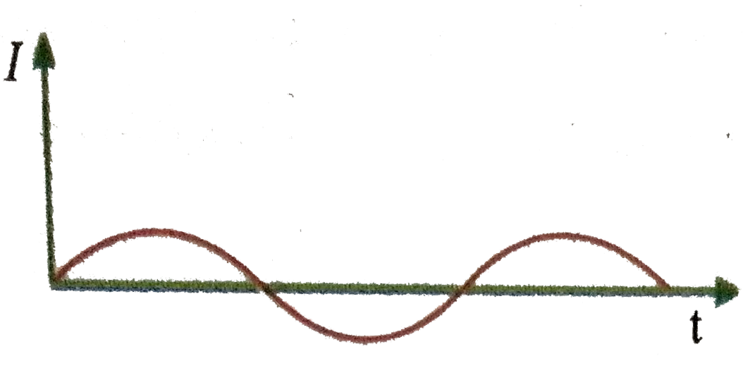 B
B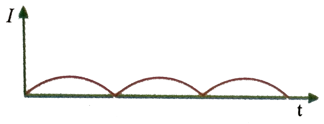 C
C D
D
Given cicuit work as a full wave rectifier then input and output terminals will be respectively
View SolutionDraw the circuit diagram of a full wave rectifier. Explain its working showing its input and output waveforms.
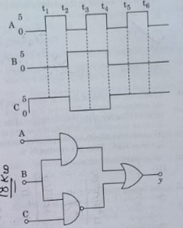
View SolutionFor given circuit the input digital signals are applied at terminal A,B, C. What would be output at terminals?
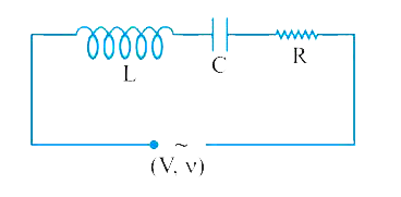
View SolutionThe series L–C–R circuit shown in fig. is in resonance state. What is the voltage across the inductor?
View SolutionDraw a circuit diagram of a full-wave rectifier. Explain its working principle. Draw the input/output wave forms indicating clearly the function of the two diode used.
View Solution

