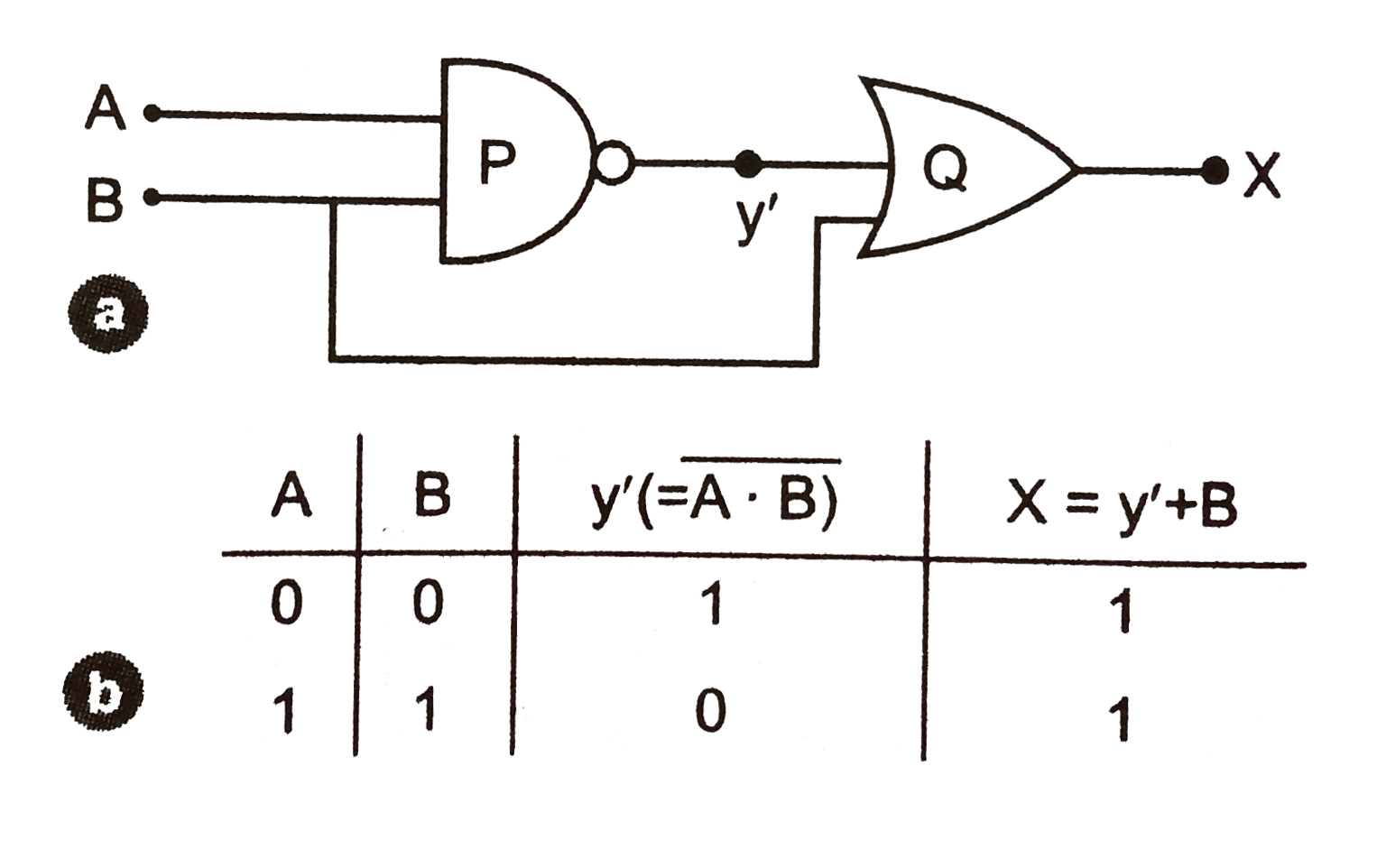
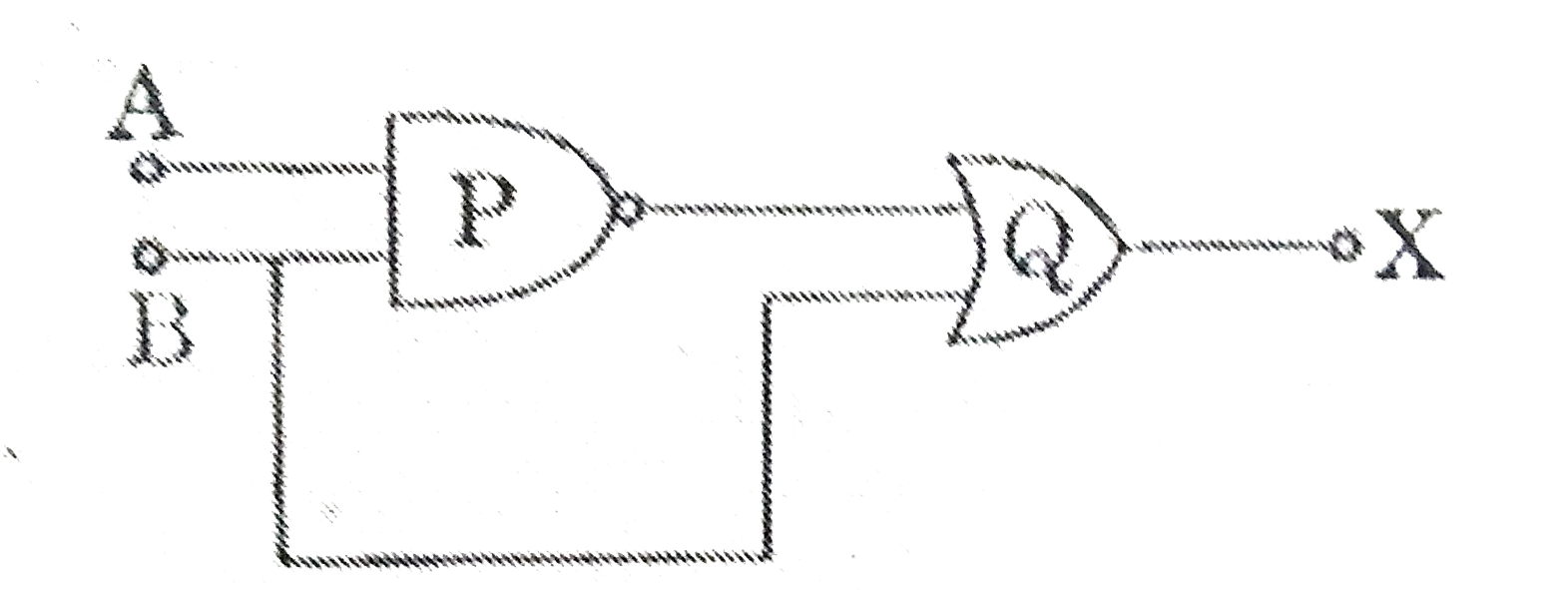
Identify the logic gates marked 'P' and 'Q' in the given circuit. Write the truth table for the combination.

Gate
Gate
Truth table :

Topper's Solved these Questions
- SEMI-CONDUCTORS ELECTRONICSBOOK - OSWAAL PUBLICATIONCHAPTER - SEMI-CONDUCTORS ELECTRONICSEXERCISE - TOPIC -4 LOGIC GATES (SHORT ANSWER TYPE QUESTIONS-II)
2 Videos
- SEMI-CONDUCTORS ELECTRONICSBOOK - OSWAAL PUBLICATIONCHAPTER - SEMI-CONDUCTORS ELECTRONICSEXERCISE - TOPIC -4 LOGIC GATES (NUMERICAL PROBLEMS)
4 Videos
- SEMI-CONDUCTORS ELECTRONICSBOOK - OSWAAL PUBLICATIONCHAPTER - SEMI-CONDUCTORS ELECTRONICSEXERCISE - TOPIC -4 LOGIC GATES (VERY SHORT ANSWER TYPE QUESTIONS)
3 Videos
- Sample Paper 8BOOK - OSWAAL PUBLICATIONCHAPTER - Sample Paper 8EXERCISE - Exercise
37 Videos
- SOLVED PAPER (II PUC JULY 2016)BOOK - OSWAAL PUBLICATIONCHAPTER - SOLVED PAPER (II PUC JULY 2016)EXERCISE - PART D
11 Videos
Similar Questions
Identify the logic gates marked P and Q in the circuit Fig. Write the truth table for this combination.

View SolutionIdentify the logic gates marked P and Q in the circuit Fig. Write the truth table for this combination.

View SolutionWrite the truth table for the given combination of gates

View SolutionIdentify the logic gates marked P and Q in the given logic circuit Fig. Write down then output at X for the inputs
(i) A=0,B=0 and (ii) A=1,B=1.

View Solution(i) Identify the logic gates marked P and Q in the given logic circuit.

(ii) Write down the output at X for the inputs A = 0 , B = 0 and A = 1 , B = 1.
View Solution(i) Identify the logic gates marked P and Q in the given logic circuit.

(ii) Write down the output at X for the inputs A = 0 , B = 0 and A = 1 , B = 1.
View Solution(i) Identify the logic gates marked P and Q in the given logic circuit Fig.

(ii) Write down the output at X for the inputs A=0,B=0 and A=1,B=1.
View Solution(i) Identify the logic gates marked P and Q in the given logic circuit Fig.

(ii) Write down the output at X for the inputs A=0,B=0 and A=1,B=1.
View SolutionIdentify the logic gates marked P and Q in the given logic circuit. Write down the Boolean expression for this logic circuit and truth table.

View SolutionIdentify the gates P and Q shown in the figure. Write the truth table for the combination of the gates shown.

Name the equivalent gate representing this circuit and write its logic symbol.
View Solution
